
Related Manuals for Bosch TRANSFLOW j-45096


Summary of Contents for Bosch TRANSFLOW j-45096
- Page 1 Transmission Cooling System J-45096 Operation Manual TRANSFLOW Transmission Cooling System Service Tool J-45096...
- Page 2 Safety Precautions WARNING: TO PREVENT PERSONAL INJURY AND/OR DAMAGE TO EQUIPMENT: • ALLOW ONLY QUALIFIED PERSONNEL TO OPERATE THE UNIT. Before oper- ating the unit, read and follow the instructions and warnings in this manual. If the operator cannot read English, operating instructions and safety pre- cautions must be read and discussed in the operator’s native language.
-
Page 3: Table Of Contents
Table of Contents Introduction Glossary of Terms ......................2 Equipment Specifications ....................2 Component Location Overview Front View .......................... 3 Rear View ........................... 3 Control Panel ........................4 Set-Up Instructions Initial Set-Up Instructions ....................5 Waste Vessel Drain Set Up ....................6 Power Up ........................... -
Page 4: Introduction
Introduction The TransFlow machine is a product designed to measure the transmission oil cooler (T.O.C.) oil flow capability and to remove contaminated oil from the T.O.C. system after a transmission repair. Measuring the transmission cooler system oil flow rate determines if the cooler meets the current GM flow rate specification. -
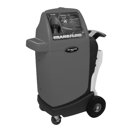
Page 5: Component Location Overview Front View
Component Location Overview Front View Operation Instructions ATF Fill Port Convenient Handle for Cord and Control Panel Hose Storage Waste Oil Vessel Polypropylene Cabinet for Durability Large Wheels for Mobility across Air Lines, Power Cords, and Grates Locking Casters Rear View Waste Oil Inlet Shop Air... -
Page 6: Control Panel
Control Panel Red light indicates when machine is pressurized Main Function Switch LCD Display Window Operating Instructions ATF Fill Port Main Power Switch Main Function Switch The following table provides a quick reference for the main function switch positions: Switch Position Description Flush Allows pressurized automatic transmission fluid with a high pressure pulse... -
Page 7: Set-Up Instructions
Set-Up Instructions Initial Set-Up 1. Remove the TransFlow unit from the packag- ing. 2. Locate the accessory package and remove the black supply hose and the clear waste hose. See Figure 1. Also locate and remove the two hose storage brackets. Figure 3 8. -
Page 8: Waste Vessel Drain Set Up
Set-up Instructions contd. The waste and supply hoses can be stored on Important: Dispose of the waste atF in these brackets when not in use. See Figure 5. accordance with all applicable federal, state and local requirements. 1. If draining from the bottom of the waste vessel, first remove the drain fitting cap plug by turning the cap plug counterclockwise while supporting the hexagonal drain fitting. - Page 9 Set-up Instructions contd. 3. Use a pencil to trace the drain support brack- et’s position at the three indicated locations. You should have two horizontal lines drawn on the bracket and one vertical line drawn on the plastic base to indicate the vertical and horizontal location of the bracket.
-
Page 10: Power Up
8. Secure the drain support bracket with the two 12. To complete the waste vessel drain set up, screws included in the accessory package. connect the fitting of your choice to the male See Figure 6. 1/2" pipe that is now installed. See Figure 8. Figure 6 Figure 8 9. -
Page 11: Transflow Self-Test
2. Verify that the main function switch is in the TransFlow Self-Test IDLE position. Place the main power switch Important: Whenever a cooler fails the flow (see Control Panel graphic on page 4 for its test, disconnect from the cooler lines and run location) in the ON position, and wait for the the self-test procedure to verify flow is 2.0 gpm IDLE screen to initialize. - Page 12 TransFlow Self-Test contd. 3. Reinstall and tighten the fill port cap. 8. Place the main function switch in the FLOW 4. Locate the 5/16" TransFlow adapter position. After the tester pressurizes, the (J-45096-21) and the 3/8" TransFlow adapter LCD display should indicate a flow rate. See (J-45096-22) from the accessory package.
-
Page 13: Operating Instructions
Operating Instructions 6. Fill the supply tank with Dexron VI ® ATF, or Machine Set-Up 1. Drain the waste oil vessel. (Refer to the Waste equivalent, through the fill port. Oil Removal procedure on page 15.) If the See Figure 3. waste oil vessel is empty, proceed to step 2. -
Page 14: Flow Test/Flush Operation
Flow Test/Flush Operation STEEL T.O.C. 1. Follow the machine set-up procedure on MINIMUM Flow Rate (gpm) page 11. emperature Range 2. From the machine display, identify the tem- Steel (Degrees Fahrenheit) perature of the automatic transmission fluid 65 to 66 that is stored in the supply vessel of Trans- 67 to 70 Flow. - Page 15 Flow Test/Flush Operation contd. 6. Locate the adapters as required for the ve- hicle being tested. Refer to Transmission Cooling System Service Tool Adapters on page 17 for a complete list of adapters. 7. Connect the appropriate adapter(s) (J-35944- 201 shown as an example) to the supplied Supply TransFlow adapter J-45096-21.
- Page 16 Flow Test/Flush Operation contd. FLOW 1.0 FLUSH FLUID 14 QTS @ 75F TESTED FLUID 18 QTS flow rate Figure 9 Figure 7 Note: If the flow rate is less than 0.5 gpm, 12. Turn the main function switch to the IDLE the LCD displays an error message.
-
Page 17: Waste Oil Removal
Flow Test/Flush Operation contd. Waste Oil Removal Dispose of the waste ATF in accordance with all applicable federal, state, and local requirements. FLOW 1.0 @ 75F CYCLE 6 A10DFB2 You may use one of two methods to drain the waste oil from the waste oil vessel. The first method is to allow the waste oil to gravity drain, and the second is to use a pump (not supplied) to pump the waste oil out of the waste oil vessel. -
Page 18: Service Parts
Maintenance 1. Drain the waste oil vessel following each use. Follow the Waste Oil Removal procedure on page 15. 2. Wipe down the unit with a cloth to remove any ATF or other substances from the unit. 3. Store upright in a clean, dry location. Service Parts TransFlow Adapter . -
Page 19: Transmission Oil Cooler (T.o.c.) Adapters
Transmission Cooling System Service Tool Adapters Transmission Oil Cooler (T.O.C.) Line Adapters: Adapters that connect directly to the T.O.C. lines. TransFlow Adapters: Adapters that connect the T.O.C. line adapter to the TransFlow machine. Note: Certain vehicle’s cooler lines will thread directly onto the TransFlow Adapter without the need for a T.O.C. -
Page 20: Useful Information/Hepful Hints
ATF, remove the screen in the fill port and inspect it for debris. If no restriction is found and the fill port will still not accept ATF, contact Bosch Automotive Service Solutions at 1-800-345-2233 for If this procedure does not increase self-test flow rate technical support and service parts ordering. -
Page 21: Troubleshooting
Troubleshooting Problem Cause Solution Main power switch is on, but 1. Power supply cable not connected 1. Connect power supply cable to graphic LCD does not to battery. battery. turn on. 2. Poor power supply cable connec- 2. Check connection at positive tion. - Page 22 Notes TRANSFLOW Transmission Cooling System Service Tool J-45096...
-
Page 23: Warranty Information/Technical Support
Warranty Information/ Technical Support The J-45096 TransFlow machine is warranted against defects in materials and workmanship for one year. Contact Bosch Automotive Service Solutions for all warranty and technical concerns at: 1-800-345-2233 TRANSFLOW Transmission Cooling System Service Tool J-45096... - Page 24 Automotive Service Solutions Service Solutions U.S. LLC 28635 Mound Road Warren, MI 48092-3499 Form No. 515054 Rev. E (10/17) TRANSFLOW Transmission Cooling System Service Tool J-45096...
Need help?
Do you have a question about the TRANSFLOW j-45096 and is the answer not in the manual?
Questions and answers