Table of Contents
Advertisement
Quick Links
Advertisement
Table of Contents

Related Manuals for AKA Berkut 5


Summary of Contents for AKA Berkut 5
- Page 1 Berkut-5 VERSION 5.01 DISCRIMINATING METAL DETECTOR OPERATING INSTRUCTIONS...
-
Page 2: Table Of Contents
GENERAL INFORMATION ....................5 INCLUDED IN KIT......................5 TECHNICAL CHARACTERISTICS..................6 INTRODUCTION......................7 ASSEMBLING YOUR BERKUT 5..................8 THE FRONT PANEL......................9 THE BACK PANEL......................10 THE DISPLAY....................... . 11 STARTING UP THE DEVICE................... - Page 3 ADDITION OF THE NEW COIL ON NEW PROFILE............40 STORAGE AND SERVICE OF YOUR DETECTOR............. 40 SOME THOUGHTS ON USING YOUR NEW DETECTOR..........42 SCANNING TECHNIQUES.................... . 43 ABOUT GROUND BALANCING ..................43 IDENTIFICATION OF DIFFERENT TYPES OF OBJECTS..........44 USE OF THE PINPOINT MODE...
-
Page 4: General Information
GENERAL INFORMATION Metal detector BERKUT 5 is designed to search for and identify metal objects in the dielectric (dry sand, wood, etc.) and low conducting media (soil, brick walls, etc.). Some applications of use are: • Criminal; • Engineering; • Housing and community services, construction and fire-fighters to search for underground utilities, pipelines, cables, manhole wells etc. -
Page 5: Technical Characteristics
TECHNICAL CHARACTERISTICS Brass disk in diameter of 25 mm - 45 cm; The maximum range Detection: Large objects - 250 cm; Audio with up to 91 tones; Visual (the LCD display with the permission Indication modes: 128х64 points); All metal; Discrimination;... -
Page 6: Introduction
INTRODUCTION What is the hodograph and why is it so important? The received signal is characterized not only by its amplitude and phase, but it is also a vector quantity. Amplitude and phase depend on the electro physical parameters of objects such as conductivity, magnetic permeability, depth, geometry, etc. -
Page 7: Assembling Your Berkut 5
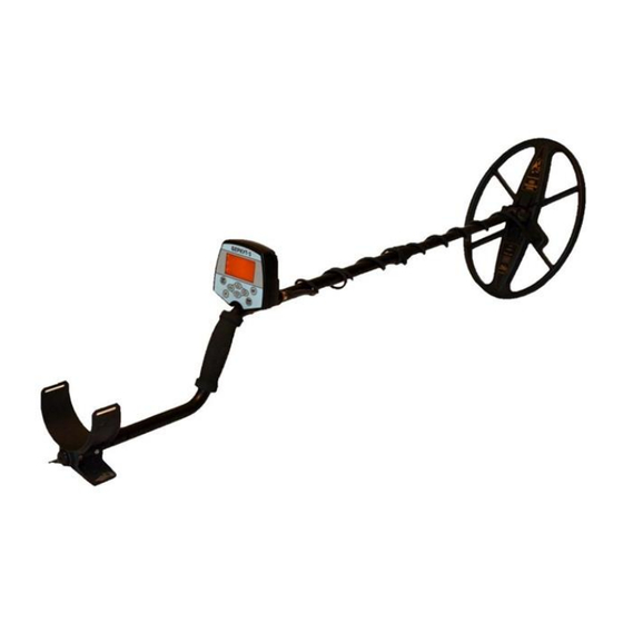
The stronger the ground minerals the greater the affect and deformation it will have on the targets signal and shape on the Hodograph (loops verses a straight line or arrow) ASSEMBLING YOUR BERKUT 5 Remove the detector from the box. When shipped the detector and parts should look like Fig. -
Page 8: The Front Panel
ATTENTION! DO not over tighten the plastic locking collars on the rod as well as the plastic Coil bolt. Once assembled your detector should look like Fig. 4. Plastic rod The coil The control box Plastic locking collar Armrest Fig. 4 THE FRONT PANEL Appearance of the front panel is shown in a Fig. -
Page 9: The Back Panel
Buttons have following appointment: Short pressing Long pressing Switch between User programs Access main menu. MENU Access Ground Balance Mode Access Coil Menu for selecting and adjusting installed coils. In the standard search mode activates Access the Menu “Display” Pinpoint mode. In Menu operations moves cursor up. -
Page 10: The Display
The on/off switch has multiple function other than just turning the detector on and off. These “other” functions can be set in menu “Other”. THE DISPLAY The Berkut 5 LCD display as shown in fig 7 S K M An TURBO... -
Page 11: Starting Up The Device
A - a mode all metals D - the discrimination mode is enabled V – When discrimination mode is enabled will indicate when Visual discrimination is on Level of a charge of the battery; T –... -
Page 12: The Start Menu
If device startup has passed successfully, the device will play a melody and will enter into the search mode (a Fig. 9): S K M An TURBO -003 Fig. 9 Otherwise, after a warning melody, there will be a warning as shown in a Fig. 10: THE COIL IS NOT COMPENSATED. - Page 13 Factory Reset, Enter Coil Setup, and Start Menu. To access the startup menu press and hold [Fn] (a Fig. 11) while turning on the device. Start Menu Factory Reset Select Coil Coil Setup Add Coil Battery: Alkaline Fig. 11 In the inclusion menu following functions are accessible: Factory Reset.
-
Page 14: Ground Balancing
To choose the coil profile desired press the buttons To select the profile activation press button [+]. To Adjust the coil. By pressing the button [+] the program enters the automatic adjustment of the coil for the current coil profile selected. To Add the new coil. - Page 15 М=002 БГ: +003 Fn: +180 Fig. 15 In the right top part of the indicator the phase of balance of a ground is represented in Degrees. On top left – The level of ground mineralization in standard units. On bottom left - Ground balancing mode (A - Automatic, Р -Manual). Slowly and smoothly lower the coil to the ground avoiding touching grass, stones, etc.
-
Page 16: Adjusting Key Parameters
in Search menu and set to preferred value (p. 28). If, after carrying out the ground balance procedure, the value of БГ differs greatly from zero this may can cause an incorrect installation of the phase parameter of the coil. To reset this value to zero simply press the button. - Page 17 COIL CURRENT (CC) [1- 2] Sets the level of current supplied to the coil. At A setting of 2 (TURBO) maximum current is applied to the coil. Maximum depth ability is achieved however operating time is decreased due to increased battery usage.
-
Page 18: Additional Parameters
as stability of the VDI will worsen. At increased settings depth of target ID will be reduced but VDI reliability and stability will increase. At a setting of 0 the device will identify a target immediately but on deep or weak targets the probability of error greatly increases. - Page 19 THE AUDIO MENU Audio Pag1 Volume: Equalizer: Volume S.S.: Keys sound: Border Fe: Num. of tones: Fig. 19 Audio Pag2 Sound freq: Length fe: Short Overload vol: Sm signal vol: Thresh volume: Fig. 20 Under the Audio Menu section are available the following parameters for adjustment: VOLUME[0-10] Sets the overall audio level of the detector.
- Page 20 Equalizer +6: +21 Fig. 21 The cursor under a column specifies which sector is currently selected. On the bottom right is displayed the VDI range for the currently selected group. The column height corresponds to the volume level of the currently selected VDI sector.
- Page 21 VALUE 10F, indication of small ferromagnetic objects is identical to the previous mode. However the sector of nonferrous metals is broken into 9 separate sectors with a division of 10 units ( VDI). The higher the VDI the higher the tone generated. The variability of the frequency of the tones is set under the parameter Frequency of Sound.
-
Page 22: Display Menu
DISPLAY MENU DISPLAY Backlight lev: Backlight: Visual disc: Accumulation: Screen scale: Fig. 22 Under the Menu DISPLAY the following parameters are available: BACKLIGHT LEVEL [1- 5] Allows the user to set the level of backlight illumination. Backlight is always set to off upon startup. The user can turn backlight on by accessing the menu or by setting the Fn hot key to turn on and off backlight. - Page 23 In the majority of the situations a normal perception of signals can be attained by setting this value to 2. When the metal detector is in mode VDI the scale of screen is established automatically such that hodographs always fit within the screen. At the lowest value of 1 small signals are amplified to maximum and large targets are slightly compressed.
- Page 24 BIG FILTER [Off/1-9] (filtering of large objects) The purpose of this filter is to eliminate an audio response from larger objects based upon their size. When set to OFF this filter is disabled. When this filter is turned on the software estimates the size of the target.If the size is LARGER than the selected value the audio response is eliminated.
-
Page 25: The Discrimination Menu
THE DISCRIMINATION MENU Discriminate Sp signal: Teach disc: Left border: Right border: Sector width: Fig. 25 In the menu DISCRIMINATE the following parameters are available: MAP serves for adjusting the discrimination characteristics of the detector. Because various objects correspond to different VDI numbers it is possible to adjust the detector to respond to certain objects while ignoring others. -
Page 26: The Other Menu
THE OTHER MENU Other Pag1 Freq offset: Pin-P Automatic: Pin-P Gain: Fn function: PWR function: Battery: NiMH Fig. 26 Other Pag2 Passage menu: Cons b-light: Num Programs: Transmitter Language Factory Reset Fig. 27 In menu OTHER the following parameters are available: FREQUENCY OFFSET[0... - Page 27 PINPOINT AUTOMATIC[Off/10- 50] Allows the user to set the time period for automatic turning off of the pinpoint mode. Times are set in approximately 10 second intervals. Automatic pinpoint can be disabled by setting parameter to off PINPOINT GAIN [0- 20] Sets the gain or sensitivity level of the static pinpoint mode.
-
Page 28: The Coil Menu
THE COIL MENU COILS Coil: D6x10-14 Editor Fig. 28 In the menu COILS the following parameters are available: COILS-Defines the coil currently installed on the device. The type of coil needs to exactly match the currently installed coil (size and frequency). More detailed description of this procedure is outlined in the section on replacing search coils. -
Page 29: Dynamic And Static Operating Modes
More in detail about adjustment of gauges it is described in section the Built in program of adjustment of gauges on p. 38. DYNAMIC AND STATIC OPERATING MODES Dynamic mode is the main mode of operation of the detector. It is characterized in that the processor constantly adjusts to relatively slow changes in ground conditions. -
Page 30: Discrimination Mode Of Search
DISCRIMINATION MODE OF SEARCH Discrimination- The ability of the detector to react to certain types of objects while ignoring others. In certain cases this is useful to improve the comfort of the search. Turning on or off discriminate is performed by pressing the button [AM/DISC]. When discrimination mode is enabled [D], briefly pressing the [AM/DISC] button the discrimination MAP will appear. -
Page 31: The Discrimination Map
In this mode the display will show the VDI graph and above it the individually selected VDI number. Next to the VDI number will be a box that will indicate whether this specific number will be accepted or rejected (discriminated). An empty box indicates this VDI number has not been included ( rejected) and will be discriminated. -
Page 32: Sector For The Special Signal
Note that within the internal memory there are stored preprogrammed discrimination maps to assist in quickly setting up the map. Choices are – Clear all, Set all, Coins, Only Ferrous, Only non ferrous. To choose one of these preset maps you must first be in the map menu then press the button [AM/DISC]. -
Page 33: Overload Mode
To quickly set the special signal to a certain class of objects you may use the fast teach mode. Insure that teach mode is set to on. Insure device is in discriminate mode (D). Scan the desired target insuring an accurate and repeatable VDI. To include the scanned target in the special signal press the button. -
Page 34: Replacing The Search Coil
released and the unit will enter the standard search mode. The current program will be program №1. And the ground balance reference point will be(0). ATTENTION! The parameters for the coils are not reset and will be retained during a factory reset The factory program №1-This program has the sensitivity set low which gives it stable response to the ground and economic battery life (low coil current). -
Page 35: Batteries
The detector should only be used with coils that have been preprogrammed into the devices memory. To make demanded options it is possible as independently by means of the built in program of adjustment of the gauge, and having addressed in firm AKA service- center. -
Page 36: Use Of Headphones
PROGRAM ADJUSTMENT OF COILS Your Berkut 5 is preconfigured to work with the coils manufactured by AKA LLC. There are a couple ways to configure the coils to work with your device by using built in... - Page 37 ADJUSTING THE NEW COIL TO THE CURRENT PROFILE If, while in use, it was necessary to make repeated adjustments to the coil, or you do not wish to use different profiles for different coils, and prefer to make adjustment at each switching of gauges (similar to some of our other models), take advantage of a mode of adjustment of the new coil under the current profile.
- Page 38 If you are using the inclusion menu then after choosing the corresponding profile press [+] After automatic adjustment of the frequency and ORT, the device will switch to the Ground Balance mode. Perform the Ground Balance procedure on pure ground, ferrite or a piece of red brick. If the GB value differs from zero significantly then press the button [ ] to zero.
-
Page 39: Scanning Techniques
SCANNING TECHNIQUES It is important to have good sweep or scanning techniques. Try to keep the coil 3-4 cm off of the ground moving the coil smoothly and evenly above the surface of the ground. Try not to make any sharp or jerking movements of the coil. The most important factor is the correct choice sweep speed. - Page 40 COUNCILS ABOUT IDENTIFICATION OF TYPES OF OBJECTS In the course of detecting you will notice those objects that are located close to the coil can complicate the ability of the detector to ID these properly either with audio or visual indications.
- Page 41 There are times, when searching in discrimination, that a target may be present in one direction but not the other. In this case it is suggested to use the “all metals” mode. This will often time help in locating these targets that may appear in direction and disappear in another.
-
Page 42: Examples Of Vdi
ABOUT EQUALIZER USE The "EQUALIZER" function can be thought of as another form of a discriminator. You can use the equalizer to accept or reject from some groups of objects. nature signal processing some metal detectors Objects louder (e.g., foil, aluminum caps, etc. -
Page 43: Guarantee Certificates
GUARANTEE CERTIFICATES The Manufacturer guarantees working capacity металлодетектора under condition of observance by the consumer of service conditions. Warranty period of operation 24 months from the date of sale. During a warranty period the found out industrial defect It is free of charge eliminated by the manufacturer, under condition of absence of mechanical damages of the electronic block and the device gauge.
Need help?
Do you have a question about the Berkut 5 and is the answer not in the manual?
Questions and answers