Table of Contents
Advertisement
Quick Links
Download this manual
See also:
User Manual
Advertisement
Table of Contents

Related Manuals for YOKOGAWA PX8000


Summary of Contents for YOKOGAWA PX8000
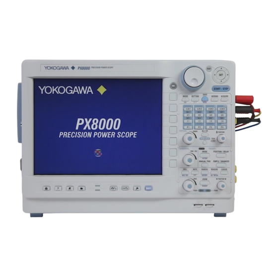
- Page 1 User’s Manual PX8000 Precision Power Scope Getting Started Guide IM PX8000-03EN 6th Edition...
-
Page 2: Product Registration
Product Registration Thank you for purchasing YOKOGAWA products. YOKOGAWA provides registered users with a variety of information and services. Please allow us to serve you best by completing the product registration form accessible from our website. http://tmi.yokogawa.com/ PIM 103-04E... - Page 3 Thank you for purchasing the PX8000 Precision Power Scope (hereinafter, “PX8000” will refer to this products). This getting started guide primarily explains the handling precautions and basic operations of the PX8000. To ensure correct use, please read this manual thoroughly before operation.
- Page 4 Revisions • 1st Edition: January 2014 • 2nd Edition: January 2014 • 3rd Edition: August 2014 • 4th Edition: December 2015 • 5th Edition: June 2017 • 6th Edition: October 2017 IM PX8000-03EN...
-
Page 5: Checking The Contents Of The Package
Unpack the box, and check the contents before operating the instrument. If the wrong items have been delivered, if items are missing, or if there is a problem with the appearance of the items, contact your nearest YOKOGAWA dealer. PX8000 Check that the product that you received is what you ordered by referring to the model name and suffix code given on the name plate on the left side panel. -
Page 6: Standard Accessories
For instructions on how to assemble the 758931, see section 2.6. Manuals Item Model or Part No. Quantity Specifications and Notes Printed manuals IM PX8000-03EN Getting Started Guide (this guide) IM PX80008-92Z1 Document for China PIM 113-01Z2 List of worldwide contacts Manual CD B8213YC Contains PDFs of the user’s manuals... - Page 7 The English folder in the manual CD contains the PDF files shown below. The CD also contains Japanese manuals. File Name Manual Title Manual No. Communication Interface.pdf PX8000 Precision Power Scope IM PX8000-17EN Communication Interface User’s Manual Features Guide&Users Manual.pdf PX8000 Precision Power Scope...
- Page 8 The combination of the 760811 (voltage module) and the 760812 (current module), or the combination of the 760811 (voltage module) and the 760813 (current module) is called a power measurement element. It is sometimes referred to simply as element in this manual. IM PX8000-03EN...
- Page 9 Cable length: 5 m Optional accesories(sold separately) are not covered by warranty of this instrument. 1 The actual voltage that can be used is the lowest voltage of the PX8000 input modules and cable specifications. 2 For details on the safety standard, see the manual that came with the 701926. Be sure to connect the GND lead provided with the 701926 to the functional ground terminal of the PX8000.
- Page 10 701959), alligator adapter (758922 or 758929), or fork terminal adapter (758921). Spare Parts (Sold Separately) The spare parts below are available for purchase separately. Check that all contents are present and undamaged. For information about ordering spare parts, contact your nearest YOKOGAWA dealer. Name Part No. Minimum Q’ty...
-
Page 11: Safety Precautions
YOKOGAWA assumes no liability for the customer’s failure to comply with these requirements. This manual is an essential part of the product; keep it in a safe place for future reference. Yokogawa Electric Corporation assumes no liability for the customer’s failure to comply with these requirements. - Page 12 To prevent the possibility of electric shock or fire, be sure to use the power cord supplied by YOKOGAWA. The main power plug must be plugged into an outlet with a protective earth terminal. Do not invalidate this protection by using an extension cord without protective earth grounding.
- Page 13 • To prevent the possibility of electric shock, be sure to furnish protective earth grounding of the PX8000. • To prevent the possibility of electric shock, be sure to fasten the module screws. Otherwise, the electrical protection function and the mechanical protection function will not be activated.
- Page 14 Be sure to connect the GND lead of the high voltage differential probe (the 701926) to the functional ground terminal of the PX8000. High voltage may appear at the BNC of the high voltage differential probe. Also, be sure to connect the GND lead to the PX8000 before you connect to the device under measurement.
- Page 15 Pour éviter tout risque de choc électrique ou d’incendie, toujours utiliser le cordon d’alimentation fourni par YOKOGAWA. La fiche doit être branchée sur une prise secteur raccordée à la terre. En cas d’utilisation d’une rallonge, celleci doit être impérativement reliée à la terre. Ne pas utiliser le cordon d’alimentation fourni avec l’instrument pour tout autre appareil.
- Page 16 • Pour éviter tout risque de choc électrique, toujours relier le PX8000 à la terre. • Pour éviter tout risque de choc électrique, toujours serrer les vis des modules, à défaut de quoi les fonctions de protection électrique et de protection mécanique ne seront pas activées.
- Page 17 Veiller à brancher le câble GND (Terre) de la sonde différentielle haute tension (réf. 701926) sur la borne de terre fonctionnelle du PX8000. Le connecteur BNC de la sonde différentielle peut présenter une tension élevée. De plus, veiller à brancher le câble GND au PX8000 avant de le brancher sur l’appareil à mesurer.
-
Page 18: Sales In Each Country Or Region
Authorized Representative in the EEA Yokogawa Europe B.V. is the authorized representative of Yokogawa Test & Measurement Corporation for this product in the EEA. To contact Yokogawa Europe B.V., see the separate list of worldwide contacts, PIM 113-01Z2. IM PX8000-03EN... -
Page 19: Symbols And Notation Used In This Manual
Note Calls attention to information that is important for proper operation of the instrument. xvii IM PX8000-03EN... -
Page 20: Table Of Contents
Using USB Keyboards and Mouse Devices ..............3-6 Setting the Menu and Message Languages ..............3-11 Synchronizing the Clock ....................3-12 Initializing Settings ......................3-13 Calibrating the PX8000 ....................3-14 Starting and Stopping Waveform Acquisition ..............3-16 Displaying Help ......................3-17 Chapter 4 Operation Examples Setting the Voltage Range .................... - Page 21 Appendix Appendix 1 How to Make Accurate Measurements .............. App-1 Appendix 2 Relationship between the Time Axis Setting, Record Length, and Sample Rate ..App-3 Appendix 3 Relationship between the Record Length and the Acquisition Mode ....App-6 IM PX8000-03EN...
-
Page 22: Chapter 1 Names And Functions Of Parts
Chapter 1 Names and Functions of Parts Top Panel, Front Panel, Right Side Panel, and Left Side Panel Top Panel Handle Vent Built-in printer (optional) You can print the display. Index IM PX8000-03EN... - Page 23 Functional ground terminal Connect a ground wire to this terminal when performing probe correction. Remote indicator On: Remote mode Off: Local mode Harmonics enable indicator Illuminates when harmonic measurement is possible. KEY PROTECT key Locks the keys. → Section 1.2 IM PX8000-03EN...
-
Page 24: Right Side Panel
Explanation → Section 2.11 Fan stop indicator Displays the detection of fan stop Explanation → Section 2.11 Sensor power supply terminal Explanation → Section 2.11 Shunt resistor box ground terminal Connect the shunt resistor box ground terminal. → Section 2.11 IM PX8000-03EN... - Page 25 The following 4 input modules are available. Voltage Module Current Module Current Module VOLTAGE CURRENT CURRENT (model: 760812) (model: 760811) (model: 760813) External current Voltage input sensor input terminal terminal Direct input Direct input terminal terminal AUX Module (model: 760851) Signal input terminal (2ch) IM PX8000-03EN...
-
Page 26: Vent
Index • Trigger source Ethernet port • Synchronization source Use to connect the PX8000 to a LAN. • PLL source Explanation about how to use • Math period (Ext Gate) → Feature’s guide and communication Explanation about how to use interface user’s manual... -
Page 27: Panel Keys And Knobs
U1 to U4, I1 to I4, and P1 to P4. This knob has a push switch. You can press the knob to reset the position to 0.00 div. IM PX8000-03EN... - Page 28 Press SHIFT and then MODE to display a menu for configuring action-on settings. POSITION/DELAY Key Press this key to set the trigger position and the trigger delay. MANUAL TRIG Key Press this key to make the PX8000 trigger regardless of the trigger settings. SIMPLE/ENHANCED Key Index Displays a trigger setup menu.
- Page 29 Press the MAG knob to switch the zoom box whose zoom factor is set by it. ◄POSITION► Knob (Zoom POSITION knob) Use this knob to set the zoom position. This knob has a push switch. Press the POSITION knob to switch the zoom box whose zoom position is set by it. IM PX8000-03EN...
- Page 30 You can also use the ▲▼ keys to select setup items. START/STOP Key Starts and stops waveform acquisition according to the trigger mode. The key is illuminated while the PX8000 is acquiring waveforms. DISPLAY MODE Key Displays a menu used to set the display mode.
-
Page 31: Help Key
CAUTION Do not push the knob sideways with strong force. Doing so may break the knobs. French ATTENTION Ne pas enfoncer les boutons latéralement en employant une force excessive. Cela pourrait les endommager, voire les casser. 1-10 IM PX8000-03EN... -
Page 32: Screens
Waiting for trigger In other situations, the reference is the trigger time. Pre-Trigger :Acquiring pre data Post-Trigger :Acquiring post data Acquiring Roll Mode Note The PX8000 LCD may include a few defective pixels. For details, see section 7.4, “Display.” 1-11 IM PX8000-03EN... - Page 33 (AUX) range, a peak over-range message shown below blinks. In this condition, the PX8000 does not make measurements even when a high voltage or large current is being received. Consequently, there is no way of knowing that such input is being received.
-
Page 34: Display Modes
Frequency of the PLL source Message Display modes For details on numeric data display and waveform display, see the following chapters in the Features Guide, IM PX8000-01EN. • Numeric Data Display : Section 8 • Waveform Display : Section 10 •... -
Page 35: System Configuration
(remote control through the use of commands) USB PERIPHERAL interface • Waveform data Saving/loading of data • Numeric data • Setup data External USB device • Image data • FTP server • FTP client USB memory/SD memory card Ethernet interface Printer server 1-14 IM PX8000-03EN... -
Page 36: Chapter 2 Making Preparations For Measurements
Since the LCD screen is very vulnerable and can be easily scratched, do not allow any sharp objects near it. Also it should not be exposed to vibrations and shocks. Unplug during Extended Non-Use Turn off the power to the circuit under measurement and the instrument and remove the power cord from the outlet. IM PX8000-03EN... - Page 37 When cleaning the case or the operation panel, turn off the circuit under measurement and the instrument and remove the instrument’s power cord from the outlet. Then, wipe the instrument lightly with a clean dry cloth. Do not use chemicals such as benzene or thinner. Doing so may cause discoloring and deformation. IM PX8000-03EN...
-
Page 38: Installing The Instrument
There are inlet holes on the bottom side of the instrument. There are also vent holes for the cooling fan on the left side panel and the top panel. To prevent internal overheating, allow for enough space around the instrument (see the figure below) and do not block the inlet and exhaust holes. IM PX8000-03EN... - Page 39 Ambient Temperature and Humidity Ambient temperature: 5 to 40°C (when the PX8000 is installed horizontally) Ambient temperature: 5 to 35°C (when the PX8000 is installed with the rear panel facing down) Ambient humidity: 20 to 80% RH (when the printer is not used; no condensation)
- Page 40 Stand Models with the Sensor Power Supply (/PD, or /PD2) Option Note The ambient temperature in which the PX8000 can be used (operating environment temperature) varies depending on the installation orientation. See “Ambient Temperature and Humidity” above. Index WARNING •...
- Page 41 • Near a strong source of heat or moisture • Where water, oil, or chemicals may splash onto the instrument We recommend that the instrument be stored in an environment where the temperature is between 5°C and 40°C. IM PX8000-03EN...
-
Page 42: Installing Input Modules
• To prevent the possibility of electric shock, be sure to connect the GND lead of the high voltage differential probe (the 701926) to the functional ground terminal of the PX8000 before you connect to the device under measurement. High voltage may appear at the BNC of the high voltage differential probe. - Page 43 • Pour éviter tout risque de choc électrique, veiller à brancher le câble GND de la sonde différentielle haute tension (701926) sur la borne de terre fonctionnelle du PX8000 avant de brancher l’appareil à mesurer. Le connecteur BNC de la sonde différentielle peut présenter une tension élevée.
- Page 44 You can check the instrument number of the pairing module. For details, see “Overview (Overview)” in chapter 26, “Other Features” of the features guide, IM PX8000-01EN. • If you replace one installed input module with another, the settings for the channel will be reset to their defaults when the power is turned on.
- Page 45 Make sure that the instrument’s power switch is off. Loosen the two screws that are fastened to the input module. Hold the two handles at the top and bottom of the input module, and pull it out. 2-10 IM PX8000-03EN...
- Page 46 ≤ 6 mW If the instrument is used in a manner not specified in this manual, the protection provided by the instrument may be impaired. YOKOGAWA assumes no liability for the customer’s failure to comply with these warnings and requirements.
-
Page 47: Connecting To A Power Supply And Turning The Power Switch On And Off
OFF. • Pour éviter tout risque de choc électrique ou d’incendie, utiliser le cordon d’alimentation fourni par YOKOGAWA et prévu pour l’instrument. • Relier l’instrument à la terre pour éviter tout risque de choc électrique. Brancher le cordon d’alimentation sur une prise de courant à... - Page 48 * The instrument can use a 100 V or a 200 V power supply. Check that the voltage supplied to the PX8000 is less than or equal to the maximum rated voltage of the provided power cord (see page iii) before using it.
- Page 49 When the power switch is turned on, self testing and calibration start automatically. This lasts for approximately 30 seconds. When the PX8000 starts normally, the screen that was displayed immediately before the power was turned off appears. Check that the PX8000 has started normally before you use it. Note •...
-
Page 50: Precautions When Wiring The Circuit Under Measurement
• When using a shunt-type current sensor as an external current sensor, turn off the circuit under measurement before you connect the sensor. Connecting or removing the sensor while the power is on is dangerous. 2-15 IM PX8000-03EN... - Page 51 EN61010-2-030 standard. Use the 760813 (current module) instead. If 760812s (current modules) and 760813 (current modules) are installed simultaneously in the PX8000, be careful not to connect a circuit under measurement whose common-mode voltage exceeds 600 V to a 760812 (current module).
- Page 52 Use measurement cables with dielectric strengths and current capacities that are appropriate for the voltage or current being measured. Attaching a measurement cable to this product may cause radio interference in which case the user will be required to correct the interference. Index 2-17 IM PX8000-03EN...
- Page 53 • Lors de l’utilisation d’un capteur de courant de type shunt en guise de capteur de courant externe, mettre le circuit à mesurer hors tension avant de brancher le capteur. Il est dangereux de brancher ou de débrancher le capteur lorsque le circuit est sous tension. 2-18 IM PX8000-03EN...
- Page 54 760813 (module de courant). En cas d’installation simultanée de 760812 (modules de courant) et de 760813 (modules de courant) dans le PX8000, veiller à ne pas brancher de circuit à mesurer dont la tension de maintien dépasse 600 V, sur un 760812 (module de courant).
- Page 55 • To measure the apparent power and power factor more accurately on an unbalanced three-phase circuit, we recommend that you use the three-voltage, three-current method (3V3A). 2-20 IM PX8000-03EN...
-
Page 56: Assembling The Adapters For The Voltage Or Current Input Terminals
Assembling the Adapters for the Voltage or Current Input Terminals Voltage Input Terminals When connecting a measurement cable to a PX8000 voltage input terminal, use the included B8213ZD Safety Terminal Adapter or the 758923 Safety Terminal Adapter (sold separately). B8213ZD Safety Terminal Adapter... - Page 57 2.6 Assembling the Adapters for the Voltage or Current Input Terminals Current Input Terminals When connecting a measurement cable to a PX8000 current input terminal, use the included B8213ZA Safety Terminal Adapter. B8213ZA Safety Terminal Adapter Cover Internal insulator Plug When using the B8213ZA Safety Terminal Adapter, assemble it according to the following procedure.
- Page 58 Cable straps are not supplied with the PX8000. Please obtain off-the-shelf cable straps. Pass a cable strap through the hole at the bottom of the current module.
- Page 59 2.6 Assembling the Adapters for the Voltage or Current Input Terminals Explanation Wire the adapters that come with the PX8000 or the adapters and various sensors that are sold separately as shown below: Wiring to a Voltage Input Terminal Voltage under...
- Page 60 External current sensor input connector * A current sensor that outputs voltage cannot be used with the 760813 (current module). * The current input terminal and external current sensor input connector on the same module cannot be wired (used) simultaneously. Index 2-25 IM PX8000-03EN...
-
Page 61: Wiring For Accurately Measuring A Single-Phase Device
± ± LOAD LOAD SOURCE SOURCE ± ± ± ± Explanation For details on the effects of stray capacitance and the effects of the measured voltage and current amplitudes, see appendix 1, “How to Make Accurate Measurements.” 2-26 IM PX8000-03EN... -
Page 62: Guide For Selecting The Method Used To Measure The Power
Direct input → section 2.9 Direct input is not possible. Current Clamp-type current sensor wiring → section 2.11 (current output type) → section 2.11 Current transformer (CT) 2: Voltage: 1000 V or less (rating voltage of EN61010-2-030) 2-27 IM PX8000-03EN... -
Page 63: Wiring The Circuit Under Measurement For Direct Input
• The terminals are safety banana jacks (male) that are 4 mm in diameter. • Only insert a safety terminal whose conductive parts are not exposed into a current input terminal. • If you are using the included B8213ZA Safety Terminal Adapter, see section 2.6. B8213ZA Current input terminals PX8000 2-28 IM PX8000-03EN... - Page 64 électroniquement à l’intérieur de l’instrument, ce qui présente un danger. Connecting to the PX8000 In the wiring examples that follow, the PX8000 elements, voltage input terminals, and current input Index terminals are simplified as shown in the following figure.
- Page 65 LOAD ± ± ± ± Element 1 Element 1 LOAD SOURCE LOAD SOURCE ± ± ± ± SOURCE LOAD SOURCE LOAD ± ± ± ± Element 1 Element 1 ± ± LOAD LOAD SOURCE SOURCE ± ± 2-30 IM PX8000-03EN...
- Page 66 If four elements are available, one three-phase, four-wire system can be set up (elements 1, 2, and 3 Index or elements 2, 3, and 4). LOAD SOURCE ± SOURCE ± LOAD ± ± ± ± ± ± ± ± ± ± Element 1 Element 2 Element 3 (U1, I1) (U2, I2) (U3, I3) 2-31 IM PX8000-03EN...
- Page 67 (U2, I2) (U3, I3) Note For details about the relationship between the wiring system and how measured and computed values are determined, see appendix 1, “Symbols and Determination of Measurement Functions.” in the features guide, IM PX8000-01EN. 2-32 IM PX8000-03EN...
-
Page 68: Wiring The Circuit Under Measurement When Using Current Sensors
• When using shunt-type current sensors, connect an external current sensor cable with an isolated BNC (B9284LK, sold separately) to an external current sensor input connector. Index Shunt-type current sensor External current sensor input connector B9284LK OUT H PX8000 ± OUT L 2-33 IM PX8000-03EN... - Page 69 ) between the sensor and the instrument to reduce the effects of common mode voltage. Take safety and error reduction into consideration when constructing external current sensor cables. PX8000 Voltage input terminals ± LOAD External current sensor input connector Shunt-type current sensor 2-34 IM PX8000-03EN...
- Page 70 De plus, lorsque la tension du circuit à mesurer est appliquée aux bornes d’entrée de capteur de courant externe, ne pas toucher les bornes d’entrée de courant, car elles sont connectées électroniquement à l’intérieur de l’instrument, ce qui présente un danger. 2-35 IM PX8000-03EN...
- Page 71 2.10 Wiring the Circuit under Measurement When Using Current Sensors Connecting to the PX8000 In the wiring examples that follow, the PX8000 elements, voltage input terminals, and current input terminals are simplified as shown in the following figure. PX8000 ±...
- Page 72 Earth side OUT L OUT H ± Element 1 Wiring Example of a Single-Phase, Three-Wire System (1P3W) Index with Shunt-Type Current Sensors SOURCE LOAD OUT H OUT L OUT H OUT L ± ± Element 1 Element 2 2-37 IM PX8000-03EN...
- Page 73 Element 2 Element 3 Note For details about the relationship between the wiring system and how measured and computed values are determined, see appendix 1, “Symbols and Determination of Measurement Functions.” in the features guide, IM PX8000-01EN. 2-38 IM PX8000-03EN...
-
Page 74: Wiring The Circuit Under Measurement When Using A Voltage Or Current Transformer
Also, when the voltage of the circuit under measurement is being applied to the external current sensor input terminals, do not touch the current input terminals. Doing so is dangerous because the terminals are electrically connected inside the instrument. 2-39 IM PX8000-03EN... - Page 75 Models with the sensor power supply option can supply power to YOKOGAWA’s CT60/CT200/CT1000/ CT2000A AC/DC current sensors. When connecting a CT60/CT200/CT1000 to the PX8000, connect the current sensor cable (sold separately) and the shunt resistor box as shown below. Current sensor cable...
- Page 76 Before connecting the shunt resistor box to the CT with the current sensor cable, be sure to connect the GND lead of the shunt resistor box to the functional ground terminal on the right side panel of the PX8000. Not doing so is dangerous as high voltage may appear in the BNC. CAUTION •...
- Page 77 • Red: Fan stop detected. The power supply to all channels is stopped.* * To resume the power supply, remove the root cause of the overcurrent, and then restart the PX8000. If the indicator still lights red after the PX8000 is restarted, the PX8000 needs to be repaired.
- Page 78 Set Sensor Preset and CT Preset according to the instructions in section 2.7, “Displaying the Menu for Configuring All Channels,” in the User’s Manual. If the configuration is not appropriate, measured values will not be read correctly. 2-43 IM PX8000-03EN...
- Page 79 To measure the apparent power and power factor more accurately on an unbalanced three-phase circuit, we recommend that you use the three-voltage, three-current method (3V3A). Connecting to the PX8000 In the wiring examples that follow, the PX8000 elements, voltage input terminals, and current input terminals are simplified as shown in the following figure. PX8000 ±...
- Page 80 L CT Index ± ± ± ± Element 1 Element 1 Wiring Example of a Single-Phase, Three-Wire System (1P3W) with VTs and CTs SOURCE LOAD L CT L CT ± ± ± ± Element 1 Element 2 2-45 IM PX8000-03EN...
- Page 81 Element 2 Element 3 Note For details about the relationship between the wiring system and how measured and computed values are determined, see appendix 1, “Symbols and Determination of Measurement Functions.” in the features guide, IM PX8000-01EN. 2-46 IM PX8000-03EN...
-
Page 82: Connecting Probes Or Bnc Cables To Aux Modules
• Be sure to connect the GND lead of the high voltage differential probe (the 701926) to the functional ground terminal of the PX8000 before you connect to the device under measurement. High voltage may appear at the BNC of the high voltage differential probe. - Page 83 • Veiller à brancher le câble GND de la sonde différentielle haute tension (701926) sur la borne de terre fonctionnelle du PX8000 avant de brancher l’appareil à mesurer. Le connecteur BNC de la sonde différentielle peut présenter une tension élevée.
- Page 84 2.12 Connecting Probes or BNC Cables to AUX Modules CAUTION Do not use the probe power supply terminals (optional) on the right side panel of the PX8000 for purposes other than supplying power to the probes. In addition, observe the number of probes that can be used that is indicated in the table.
-
Page 85: 2.13 Correcting The Probe Phase
Trigger slope: Rising • Trigger level: 500 mV For the configuration procedure, see the Features Guide, IM PX8000-01EN. Insert a screwdriver into the phase adjustment hole, and turn the variable capacitor so that the displayed waveform is an appropriate square wave. - Page 86 Computation: 1 V ± 10 % Differences in the Waveform due to the Phase Correction of the Probe Too much adjustment Not enough adjustment Correct waveform (increased gain in the high (reduced gain in the high frequency band) frequency band) Index 2-51 IM PX8000-03EN...
-
Page 87: Loading Roll Paper Into The Built-In Printer (Optional)
Printer Roll Paper Only use roll paper specifically made for use with the PX8000. The PX8000 comes with one set of roll paper included. Use this when you first load roll paper into the built-in printer. When you need a new supply of roll paper, please contact your nearest YOKOGAWA dealer. - Page 88 Raise the handle. Printer cover OPEN COVER button Press the OPEN COVER button to open the printer cover. Index Set the roll paper with the same orientation as shown in the figure Roll paper cutter section Print head 2-53 IM PX8000-03EN...
- Page 89 2.14 Loading Roll Paper into the Built-In Printer (Optional) Guide Close the cover, and press LOCK Align the ends of the roll paper with on the center of the cover the guides, and set the roll in place. until you hear a click. 2-54 IM PX8000-03EN...
-
Page 90: Chapter 3 Common Operations
If you press the ESC key when a setup menu or available settings are displayed, the screen returns to the menu level above the current one. If you press the ESC key when the highest level menu is displayed, the setup menu disappears. IM PX8000-03EN... - Page 91 If you press RESET when you are using the jog shuttle to set a value or select an item, the setting is reset to its default value (depending on the operating state of the PX8000, the setting may not be reset).
-
Page 92: Entering Values And Strings
After you enter the value, press ENTER to confirm it. Use the keypad to enter the value. Note Index Some items that you can set using the jog shuttle are reset to their default values when you press the RESET key. IM PX8000-03EN... - Page 93 Deletes the previous character Confirms the characters that you have entered Select to enter a string from the history. List of previously entered strings After selecting an item using the jog shuttle or the arrow keys, press SET to confirm it. IM PX8000-03EN...
- Page 94 MS-DOS limitations: AUX, CON, PRN, NUL, CLOCK, COM1 to COM9, and LPT1 to LPT9 For details on file name limitations, see the Features Guide, IM PX8000-01EN. • When a character string is confirmed, it is stored in a list of previously entered strings. Up to 50 character strings are stored.
-
Page 95: Using Usb Keyboards And Mouse Devices
USB cable regardless of whether the PX8000 power switch is turned on (hot-plug support). Connect the type A connector of the USB cable to the PX8000, and connect the type B connector to the keyboard. When the power switch is on, the keyboard is detected and enabled approximately 6 seconds after it is connected. -
Page 96: Connection Procedure
Some settings cannot be configured by a mouse without a wheel. Connection Procedure To connect a USB mouse to the PX8000, use one of the USB ports for peripherals. You can connect or disconnect the USB mouse at any time regardless of whether the PX8000 is on or off (hot-plugging is supported). - Page 97 • Operations That Correspond to the Front Panel Keys (Top Menu) Displaying the Top Menu Right-click on the display. A menu of the PX8000 front panel keys appears. Selecting an Item from the Top Menu Click on the item that you want to select. A setup menu that corresponds to the item that you selected appears at the bottom of the display.
- Page 98 Change the value by clicking and using the mouse wheel. Click within this area to select the item that you want to set. IM PX8000-03EN...
- Page 99 Move the pointer close to the TIME/DIV value in the upper right of the display. The pointer becomes a . Rotate the mouse wheel forward to increase the TIME/DIV value, and rotate it back to decrease the value. Measurement range setting TIME/DIV setting 3-10 IM PX8000-03EN...
-
Page 100: Setting The Menu And Message Languages
3.7) using one of the following languages. The error codes that accompany error messages are the same for all languages. For more information about error messages, see chapter 25 in the Index user's manual, IM PX8000-02EN. • Japanese • English •... -
Page 101: Synchronizing The Clock
This section explains how to set the PX8000 clock, which is used to generate timestamps for measured data and files. The PX8000 is factory shipped with a set date and time. You must set the clock before you start measurements. -
Page 102: Initializing Settings
Initializing Settings You can reset the PX8000 settings to their factory default values. This feature is useful when you want to cancel all of the settings that you have entered or when you want to redo measurement from scratch. UTILITY System Config Menu Press UTILITY, the System Config soft key, and then the All Setup soft key to display the following menu. -
Page 103: Calibrating The Px8000
Calibration is performed automatically when the power switch is turned on. Notes about Calibration • Allow the PX8000 to warm up for at least 30 minutes before you execute calibration. If you execute calibration immediately after power-on, the calibrated values may drift due to temperature changes or other environmental changes. - Page 104 • OFF: Auto calibration is not executed. • AUTO: Auto calibration is executed. If calibration is executed while signals are being applied to the PX8000, we recommend that you recalibrate the PX8000 without any signals being applied to it. Index...
-
Page 105: Starting And Stopping Waveform Acquisition
The key is illuminated while the PX8000 is acquiring waveforms. Waveform Acquisition and Indicators • When the START/STOP key is illuminated, the PX8000 is acquiring waveforms. “Running” appears in the lower left of the screen. • When the START/STOP key is not illuminated, waveform acquisition is stopped. “Stopped” appears in the lower left of the screen. -
Page 106: Displaying Help
With help displayed, press a panel key to display an explanation of it. Returning to the Previous Screen To return to the previous screen, press RESET. Hiding Help Press the help key ( ) to clear help. Index 3-17 IM PX8000-03EN... -
Page 107: Chapter 4 Operation Examples
This chapter provides basic operation examples of the PX8000. The examples assume that the PX8000 is initialized as described in section 3.6. For details on each function and procedure, see the reference sections at the upper right of relevant pages. -
Page 108: Setting The Current Range
Setting the Current Range For details, see section 2.2 in the User’s Manual, IM PX8000-02EN. For the current range, set the current that corresponds to 2.5 divisions on the waveform screen. For example, if you set the current range to 1 A, the waveform display amplitude will be ±2 A. -
Page 109: Configuring The Wiring System Settings
Configuring the Wiring System Settings For details, see section 1.1 in the User’s Manual, IM PX8000-02EN. Set a wiring system that matches the connected circuit under measurement. • To measure power of a single-phase two-wire system, use the factory default wiring system setting (1P2W). -
Page 110: Setting The Horizontal Scale (Time Scale)
Setting the Horizontal Scale (Time Scale) For details, see section 2.8 in the User’s Manual, IM PX8000-02EN. Set the time for displaying acquired waveforms. Time scale Time scale Turn the TIME/DIV knob to set the time scale. The time scale is displayed in the upper right and in the top center of the screen. -
Page 111: Setting The Trigger Mode
For details, see section 3.1 in the User’s Manual, IM PX8000-02EN. Triggers are events used to display waveforms. Trigger is said to be activated when the specified trigger conditions are met, and the PX8000 enters a state in which waveforms are displayed on the screen. -
Page 112: Setting Edge Triggers
Setting Edge Triggers For details, see section 3.4 in the User’s Manual, IM PX8000-02EN. This section explains how to configure the PX8000 so that it triggers on the rising or falling edge of an input signal. Trigger Source Trigger source refers to the signal used to determine whether the specified trigger conditions are met. -
Page 113: Starting And Stopping Waveform Acquisition
Starting and Stopping Waveform Acquisition For details, see section 4.2 in the User’s Manual, IM PX8000-02EN. This section explains how to start and stop waveform acquisition. Press START/STOP to start or stop waveform acquisition. When the START/STOP key is illuminated, the PX8000 is acquiring waveforms. -
Page 114: Turning The Waveform Display On And Off
Turning the Waveform Display On and Off For details, see section 2.1 or 8.1 in the User’s Manual, IM PX8000-02EN. By factory default, the waveform displays of all input modules’ input signals are turned on. Turn on or off each waveform display depending on which waveforms you want to observe. -
Page 115: Selecting The Waveform Display Format
Selecting the Waveform Display Format For details, see section 8.1 in the User’s Manual, IM PX8000-02EN. You can select the number of divided waveform display windows to make it easier to view input waveforms and math waveforms. Set the display format. -
Page 116: 4.10 Measuring With Cursors
4.10 Measuring with Cursors For details, see section 13.2 in the User’s Manual, IM PX8000-02EN. Cursors can be placed on displayed waveforms to display the measured values at the intersections of cursors and waveforms. Set Type to Vertical. Set the source waveform. -
Page 117: Computing Values In A Specified Time Range Using The Automated Measurement Of Waveform Parameters
Range Using the Automated Measurement of Waveform Parameters For details, see section 14.1 in the User’s Manual, IM PX8000-02EN. For waveforms that are displayed on the screen, various measurement items (waveform parameters), such as maximum and minimum values, can be measured automatically and their statistics can be calculated. -
Page 118: Using Waveform Computation To Display The Trend Of The Rms Current Per Cycle
4.12 Using Waveform Computation to Display the Trend of the Rms Current per Cycle For details, see section 15.5 in the User’s Manual, IM PX8000-02EN. Waveform data can be computed using addition, subtraction, multiplication, division, FFT (power spectrum), square root, differentiation, digital filtering, and the like. -
Page 119: Chapter 5 External Signal I/O
External Trigger Input (TRIGGER IN) CAUTION Only apply signals that meet the following specifications. Signals that do not meet the specifications may damage the PX8000, because of factors such as excessive voltage. French ATTENTION N’appliquer que des signaux correspondant aux spécifications suivantes. Les autres signaux pourraient endommager le PX8000 en raison de divers facteurs, notamment la tension excessive. - Page 120 5.1 External Trigger Input (TRIGGER IN) Note You can synchronize the operation of two PX8000s by using the trigger output function. No. 1 No. 2 PX8000 PX8000 TRIG TRIG IM PX8000-03EN...
-
Page 121: Trigger Output (Trigger Out)
External Trigger Output Terminal TRIGGER When a trigger occurs, the PX8000 produces a CMOS level signal. You can set the output mode to normal or pulse. The signal level is normally high. It becomes low when a trigger occurs. Item... - Page 122 5.2 Trigger Output (TRIGGER OUT) Low Level and High Level Hold Times (In normal mode) Trigger occurrence Trigger occurrence Trigger output Post-trigger time Trigger Trigger Post Post Waveform acquisition IM PX8000-03EN...
-
Page 123: External Clock Input (Ext Clk In)
External Clock Input (EXT CLK IN) CAUTION Only apply signals that meet the following specifications. Signals that do not meet the specifications may damage the PX8000, because of factors such as excessive voltage. French ATTENTION N’appliquer que des signaux correspondant aux spécifications suivantes. Les autres signaux pourraient endommager le PX8000 en raison de divers facteurs, notamment la tension excessive. -
Page 124: Video Signal Output (Video Out (Xga))
PX8000. Video Signal Output Terminal VIDEO OUT ( XGA ) You can use video signal output to display the PX8000 screen on a monitor. Any multisync monitor that supports XGA can be connected. Item Specifications Connector type... - Page 125 Vertical sync signal Approx. 60 Hz, TTL positive logic — Connecting to a Monitor Turn off the PX8000 and the monitor. Connect the PX8000 and the monitor using an RGB cable. Turn on the PX8000 and the monitor. Index IM PX8000-03EN...
-
Page 126: Go/No-Go Determination I/O And External Start/Stop Input (Ext I/O)
• When connecting the GO/NO-GO determination signal output to another device, do not connect the wrong signal pin. Doing so may damage the PX8000 or the connected instrument. • Do not connect a USB cable to the GO/NO-GO output terminal. Doing so may damage the instrument. - Page 127 5.5 GO/NO-GO Determination I/O and External Start/Stop Input (EXT I/O) GO/NO-GO Determination I/O You can apply an external signal to the PX8000’s GO/NO-GO I/O terminal and perform GO/NO-GO determination, and you can output the results of GO/NO-GO determination from the GO/NO-GO I/O terminal.
-
Page 128: Output Signal
Result NOGO OUT GO OUT START IN is not referenced when Remote The signal remains low until the PX8000 is set to OFF; GO OUT and NO-GO OUT is ready to accept the next measurement. are output according to internal The duration is longer during output to a built-in GO/NO-GO determination. - Page 129 5.5 GO/NO-GO Determination I/O and External Start/Stop Input (EXT I/O) External Start/Stop Input (EXT I/O) You can use an external signal to start and stop the PX8000. External Start/Stop Input Terminal The External Start/Stop Input terminal and the GO/NO-GO I/O terminal are the same terminal. This terminal is used as an external start/stop input when the GO/NO-GO determination I/O function is not used (when on the GO/NO-GO menu, Mode is set to OFF).
-
Page 130: Irig Signal Input (Irig Option)
PX8000 en raison de divers facteurs, notamment la tension excessive. IRIG Signal Input Terminal IRIG You can use an IRIG (Inter Range Instrumentation Group) signal to set the time on the PX8000. Item Specifications Input connector Number of input connectors... -
Page 131: Troubleshooting, Maintenance, And Inspection
Troubleshooting Dealing with Problems • If a message appears on the screen, see chapter 25 in the user’s manual, IM PX8000-02EN. • If servicing is necessary, or if the instrument does not operate properly even after you have attempted to deal with the problem according to the instructions in this section, contact your nearest YOKOGAWA dealer. -
Page 132: Recommended Replacement Parts
Recommended Replacement Parts For part replacement, contact your nearest YOKOGAWA dealer. Part Name Lifetime Built-in printer Under normal conditions of use, equivalent of 500 rolls of printer paper (part number: B9988AE) LCD backlight Under normal conditions of use, approximately 25,000 hours The following are consumable parts. -
Page 133: Calibration And Adjustment
Calibration and Adjustment For calibration and adjustment, contact your nearest YOKOGAWA dealer. Power Measurement Calibration and Adjustment Power measurement calibration and adjustment require both voltage modules (760811) and current modules (760812/760813). Please request calibration and adjustment for the pairs of voltage and current modules that you received at the time of purchase. -
Page 134: Chapter 7 Specifications
1000 V: Maximum allowable voltage that can be measured 600 V CAT II : Rating voltage of EN61010-2-030 Do not touch the inside of the external current sensor input BNC. Current module (760813) 1000 V CAT II : Rating voltage of EN61010-2-030 IM PX8000-03EN... - Page 135 (measured voltage/applied voltage) is less than or equal to –80 dB at 50/60 Hz Bandwidth limit Select Full, 2 MHz, 1.28 MHz, 640 kHz, 320 kHz, 160 kHz, 80 kHz, 40 kHz, 20 kHz, or 10 kHz. Cutoff characteristic: –18 dB/OCT (typical, at 2 MHz) IM PX8000-03EN...
- Page 136 700929 701947 Withstand voltage: 1500 Vrms (1 minute) Allowable transient surge voltage (between the input terminals and earth): ±2100 Vpeak 7 Typical values represent typical or average values. They are not strictly guaranteed. IM PX8000-03EN...
-
Page 137: Triggering Section
The PX8000 triggers on the logical OR of multiple edge or state conditions. Pulse Width: B>Time: The PX8000 triggers when the time from when condition B is met until it is no longer met is greater than the specified time duration. Time specification: 20 ns to 10 s (in 10 ns steps) B <... -
Page 138: Time Axis
7.2 Triggering Section Item Specifications T < T1, T2 < T: The PX8000 triggers when the period of condition T is outside the specified time duration. Time specification: T1: 20 ns to 10 s in 10 ns steps T2: 30 ns to 10 s in 10 ns steps... -
Page 139: Display
Displays a bar graph of the amplitude of each harmonic Zoom Display Item Specifications Expands waveforms Up to two screens FFT Display Item Specifications Displays waveform spectrum Up to two screens X-Y Display Item Specifications Display based on specified Up to two screens X-axis and Y-axis IM PX8000-03EN... -
Page 140: Features
• 500 Hz frequency filter is ON at 500 Hz or less. • 100 Hz frequency filter is ON at 100 Hz or less. Accuracy: ±(0.1% of reading) Display resolution: 99999 Frequency measurement filter: Select OFF, 100 Hz, 500 Hz, 2 kHz, or 20 kHz. IM PX8000-03EN... - Page 141 (50 μA/current range rating) × 100% of range • Add the following accuracy values when the external current sensor range is 50 mV to 500 mV. Current: 100 μV Power: (100 μV/external current sensor range rating) × 100% of range IM PX8000-03EN...
- Page 142 AX+B mode or P1-P2 mode can be specified separately for AUX modules (valid on AUX modules). Roll mode Roll mode is enabled automatically when the trigger mode is set to auto, auto level, single, or on- start, and the time axis setting is greater than or equal to 100 ms/div. IM PX8000-03EN...
- Page 143 Maximum measurement range: 100 Mpoint Normal statistical processing Statistical processing is performed while waveforms are acquired. Cyclic statistical processing The PX8000 automatically measures the waveform parameters of the data in the acquisition memory and performs statistical processing on the parameters once per period.
-
Page 144: Fft
Display range: Set the display range by setting Center and Sensitivity. Built-in Printer (Option) Item Specifications Print system Thermal line dot system Dot density 8 dots/mm Sheet width 112 mm Index Effective recording width 104 mm (832 dots) Function Producing a hard copy of the screen 7-11 IM PX8000-03EN... -
Page 145: Storage
Mass storage devices that comply with USB Mass Storage Class Ver. 1.1 104 or 109 keyboards that comply with USB HID Class Ver. 1.1 Mouse devices that comply with USB HID Class Ver. 1.1 Power supply 5 V, 500 mA (for each port) 7-12 IM PX8000-03EN... -
Page 146: App
External Start/Stop Input Item Specifications Connector type RJ-11 modular jack Input level TTL or contact input COMP Output (Probe Compensation Signal Output Terminal) Item Specifications Output signal frequency 1 kHz ± 1% Output amplitude 1 Vp-p ± 10% 7-13 IM PX8000-03EN... - Page 147 A002, B002, A132, B122 Input impedance You can switch between 50 Ω and 5 kΩ. Maximum input voltage ±8 V Function Synchronizing the PX8000 clock Sample clock synchronization Clock sync range ±80 ppm Post-sync accuracy No drift from the input signal...
-
Page 148: 7.11 Computer Interface
USBTMC-USB488 (USB Test and Measurement Class Ver. 1.0) PC system requirements A PC with a USB port, running the English or Japanese version of Windows 7 (32 bit), Windows Vista (32 bit), or Windows XP (32 bit, SP2 or later) 7-15 IM PX8000-03EN... -
Page 149: 7.12 Displayed Items
Measurement Functions Used in Normal Measurement Measurement Functions Determined for Each Power Measurement Element For details about how the measurement function values are computed and determined, see appendix 1 in the Features Guide, IM PX8000-01EN. Item Symbols and Meanings Voltage (V) - Page 150 7.12 Displayed Items Measurement Functions (Σ Functions) Determined for Each Wiring Unit (ΣA and ΣB) For details about how the Σ function values are computed and determined, see appendix 1 in the Features Guide, IM PX8000-01EN. Item Symbols and Meanings Voltage (V) UrmsΣ: true rms value...
- Page 151 PLL source frequency. It can go up to the 500th harmonic order. The total value is determined according to the equation on page App-3 in the User’s Manual, IM PX8000-01EN, from the fundamental wave (1st harmonic) and all harmonic components (2nd harmonic to the upper limit of harmonic analysis). The DC component can also be included.
- Page 152 λΣ: total power factor 1 The total value is determined according to the equation on page App-3 in the User’s Manual, IM PX8000-01EN, from the fundamental wave (1st harmonic) and all harmonic components (2nd harmonic to the upper limit of harmonic analysis). The DC component can also be included.
- Page 153 Pulse: Displays up to 2 MHz (OF display at 10 GHz or higher if scaling is used) • Minimum display (zero suppression) Analog: None Pulse: Displays pulse frequency down to 1.8 Hz Frequencies less than 1.8 Hz are suppressed to zero. 7-20 IM PX8000-03EN...
-
Page 154: Voltage, Current, And Power Accuracies (Power Measurement Element)
400kHz < f ≤ 500kHz: ±{(0.1 + 0.004 × f*)% of reading + 0.4% of range} 500kHz < f ≤ 1MHz: ±{(0.1 + 0.004 × f*)% of reading + 4% of range} Frequency bandwidth 10 MHz (–3dB, typical) 7-21 IM PX8000-03EN... - Page 155 1 kHz to 50 kHz, add ±(0.2% of reading) to the power accuracies. • If the input is 400 Vrms or higher, add (rated range)/(maximum range) × 0.005× f of reading to the voltage and power accuracies. f: Frequency (kHz) 7-22 IM PX8000-03EN...
- Page 156 When 0 < power factor < 1 (φ: phase angle of the voltage and current) (power reading) × [(power reading error %) + (power range error %) × (power range/indicated apparent power value) + {tanφ × (influence when λ = 0)%}] 7-23 IM PX8000-03EN...
- Page 157 (10 mA range: ±6% of range (designed value)) Excludes errors due to sampling resolution and analog bandwidth limitations Accuracy at 1 year (Guaranteed accuracy period 1 year) 1.5 times the reading errors for the accuracy at 6 months 7-24 IM PX8000-03EN...
- Page 158 At least 30 minutes Operating temperature 5 to 40°C when the PX8000 is installed horizontally. 5 to 35°C when the PX8000 is installed with the rear panel facing down. Humidity 20 to 80%RH (when the printer is not used; no condensation) 35 to 80%RH (when the printer is used;...
- Page 159 EN50581 Monitoring and control instruments including industrial monitoring and control instruments Applies to products with CE marks. For information on other products, contact your nearest YOKOGAWA dealer. The overvoltage category is a value used to define the transient overvoltage condition and includes the rated impulse withstand voltage.
-
Page 160: External Dimensions
7.15 External Dimensions Unit: mm Unless otherwise specified, tolerances are ±3% (however, tolerances are ±0.3 mm when below 10 mm). Rear view Index 16.5 21.6 11.7 Models with the Sensor Power Supply (/PD, or PD2) Option 11.7 245.3 7-27 IM PX8000-03EN... -
Page 161: Appendix
Only e reduces measurement accuracy. For example, the input resistance of the current measurement circuit of the PX8000 is approximately 100 mΩ. If the load resistance is 1 kΩ, the effect on the measurement accuracy is approximately 0.01% (100 mΩ/1 kΩ). - Page 162 Effects of Stray Capacitance The effects of stray capacitance on measurement accuracy can be minimized by connecting the PX8000 current input terminal to the side of the power supply (SOURCE) that is closest to its earth potential. The internal structure of the PX8000 is explained below.
- Page 163 240 k 240 k 600 k When the time axis setting is 100 ms or greater (the settings surrounded by bold lines) and the trigger mode is Auto or Auto Level, waveforms are displayed in roll mode. App-3 IM PX8000-03EN...
-
Page 164: Appendix 2 Relationship Between The Time Axis Setting, Record Length, And Sample Rate
2.4 M 20 k 24 M When the time axis setting is 100 ms or greater (the settings surrounded by bold lines) and the trigger mode is Auto or Auto Level, waveforms are displayed in roll mode. App-4 IM PX8000-03EN... - Page 165 24 M 50 k 60 M When the time axis setting is 100 ms or greater (the settings surrounded by bold lines) and the trigger mode is Auto or Auto Level, waveforms are displayed in roll mode. App-5 IM PX8000-03EN...
-
Page 166: Appendix 3 Relationship Between The Record Length And The Acquisition Mode
/M2 Option Model (50 Mpoint) (100 Mpoint) (10 Mpoint) 100 kpoint 1000 250 kpoint 500 kpoint 1 Mpoint 2.5 Mpoint 5 Mpoint 10 Mpoint 25 Mpoint 50 Mpoint 100 Mpoint * -: This record length cannot be set. App-6 IM PX8000-03EN...
Need help?
Do you have a question about the PX8000 and is the answer not in the manual?
Questions and answers