
Subscribe to Our Youtube Channel
Related Manuals for YOKOGAWA PH200


Summary of Contents for YOKOGAWA PH200
- Page 1 Instruction Model PH200 2-wire pH transmitter Manual IM 12B6C2-E-H YOKOGAWA 6th edition...
- Page 2 OUTPUT HOLD MANUAL TEMPERATURE FAIL FLAG MENU POINTER FLAGS COMPENSATION FLAG FLAG MENU FOR MAINTE- NANCE FUNCTIONS HOLD HOLD TEMP.MAN TEMP.MAN FAIL FAIL MODE MODE MEASURED (see chapter 5) VALUE DISPLAY MEASURE MEASURE AUT.CAL AUT.CAL OUTPUT OUTPUT MAN.CAL MAN.CAL SET HOLD SET HOLD MESSAGE DISPLAY DISPLAY...
-
Page 3: Table Of Contents
CONTENTS 1. INTRODUCTION ..............1 4. COMMISSIONING..............11 1-1. Application..............1 4-1. Operations overview .............11 1-2. Required components for pH measurement ....1 4-2. Output range adjustment.....OUTPUT ...12 1-3. Identification ..............1 4-3. Set up the HOLD function ....SET HOLD..14 4-4. Sensor selection and diagnostics........16 2. - Page 4 7. SERVICE MODE..............30 7-1. Introduction ..............30 7-2. Access to service settings ...........31 7-3. Temperature function...........32 7-4. Temperature sensors ...........32 7-5. Sensor checking............33 7-6. Display resolution ............34 7-7. Signalling of fail condition ..........34 7-8. Stabilization check............34 7-9. Auto return ..............35 7-10. Buffer tables ..............35 7-11.
-
Page 5: Introduction
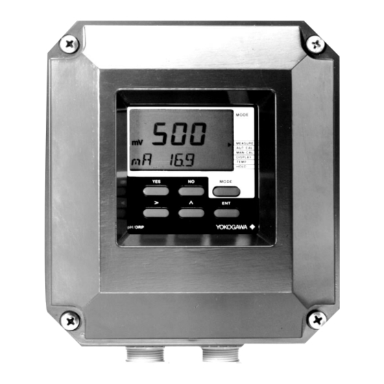
1. INTRODUCTION 1-1. Application 1-2. Required components for pH 1-3. Identification The EXA PH200 transmitter is a 2-wire pH measurement The instrument has an identification label, instrument intended to be used in industrial 1. A pH electrode and a reference electrode which is fixed to the front plate. -
Page 6: Technical Specifications
2. TECHNICAL SPECIFICATIONS 2-1. General specifications G. Housing A. Intrinsic safety – Material : Cast aluminium with chemical resi- – BASEEFA : Certified by and meets the require- stant coating ments of EEx [ia] ib IIC T4 of CENE- – Window : Flexible poly-carbonate –... -
Page 7: Functional Description
(EEPROM) for the essential in formation the operations like commissioning or fine-tuning. operating parameters are fixed in memory All this makes the EXA PH200 operate like a without the need for a battery. The software normal analogue transmitter with a number is designed with the user in mind. -
Page 8: Installation And Wiring
154 (6.06`) tions . 30 (1.18) 3-1-2. Mounting methods The EXA PH200 transmitter has universal mounting possibilities: - panel mounting using selftapping screws - surface mounting on a plate (by bolts 2x ø4 from the back) - wall mounting on a bracket (e.g. - Page 9 Option /M: Universal wall/pipe mounting kit 56 (2.2) 2x ø6.6 (0.26) 4x ø10 (0.4) 77 (3.03) (4.53) 70 (2.75) 2” Pipe 2” Pipe Pipe mounting Pipe mounting Wall mounting (vertical) (horizontal) IM 12B6C2-E-H...
-
Page 10: Wiring Of Sensors
All Yokogawa fittings have provisions for this nals of the EXA PH200 do not exceed the connection. It is usually called liquid earth in limits given in the certificate. -
Page 11: Connection Diagram For Sensors
3-2-5. Connection diagram for sensors Rd=Red, Bl=Blue, Wt=White, Single electrodes Combined electrodes + - G 11 12 14 13 17 15 16 + - G 11 12 14 13 17 15 16 Temperature - Reference pH Temperature Combined Pt 100 AgCl glass Liquid earth... -
Page 12: Wiring Of Power Supply
2-wire cable to the trans- make sure that the DC-power supply is of the EXA PH200 do not exceed the mitter. Connect the supply to the terminals according to the specifications given. - Page 13 Wiring diagrams for power supply General purpose design pH-transmitter EXA PH200G Distributor – – NOTE: The outside earth terminal should be connected to site ground by a large area conductor (e.g. a flat earth strip) for best protection against interference. Dependance of load to supply voltage 1200 1000...
- Page 14 Wiring diagrams for hazardous areas EEx ib Intrinsically safe design Certified safety barrier (CELENEC standard EEX ib [ia] IIC T4) Distributor pH-transmitter EXA PH200S Electronic current limiting barrier Vmax: 31.5 V – – lmax: 35 mA Pmax: 1,1 W Zenerbarrier with resistor Vmax: 28 V lmax: 93.3 mA...
-
Page 15: Commissioning
4. COMMISSIONING 4-1. Operations overview Routine Chapter MAINTENANCE AUT.CAL Calibration with buffer solutions Operation by keys through MAN.CAL Calibration in process closed cover DISPLAY Show or fix additional values TEMP Select automatic or manual temperature compensation HOLD Switch HOLD-function on/off COMMISSIONING OUTPUT Adjusting the output function... -
Page 16: Output Range Adjustment
4-2. Output range adjustment 1. Access output 2. Adjust low span value 3. Adjust high span value OUTPUT OUTPUT OUTPUT SET HOLD SET HOLD SET HOLD SERVICE SERVICE SERVICE MODE MODE MODE Remove cover by releasing 4 screws. Display will show *4 mA Display will show *20 mA Adjust value for low span Adjust value for high span... - Page 17 The display will always show the actual value EXAMPLE: The current to be set at the output is calcu- between -1 and 15 pH. The EXA PH200 has to be programmed for lated as follows: a range of 2 ... 12 pH. pH - pH...
-
Page 18: Set Up The Hold Function
4-3. Set up the HOLD-function 1. Access to HOLD-function 2. Activate HOLD-function 3. Select value to hold OUTPUT OUTPUT OUTPUT SET HOLD SET HOLD SET HOLD SERVICE SERVICE SERVICE MODE MODE MODE Remove cover by releasing 4 screws. Display shows actual status Display shows current setting *H.OFF = HOLD not active... - Page 19 7.00. occur. The EXA PH200 will keep the output frozen Two possibilities are generally used: during the following events: Activate the HOLD function and choose the a. Keeping the output at the LAST value a.
-
Page 20: Sensor Selection And Diagnostics
4-4-2. Selecting a temperature sensor 4-4-3. Off-line calibration checks The inputs of the EXA PH200 transmitter are The EXA PH200 has been factory set for a The EXA PH200 transmitter incorporates a free programmable for ease of retrofit on Pt100 temperature sensor to DIN standards. -
Page 21: On-Line Impedance Chacks
4-4-4. On-line impedance checks The EXA PH200 transmitter is delivered from the factory with an impedance check disab- led. To activate this impedance checking refer to §7-5. The impedance check works on both measuring and reference electrode, but not in the same way. The measuring electrode is checked for presence of a high impedance on the input side. -
Page 22: Automatic Calibration
5. MAINTENANCE 5-1. Automatic calibration 1.Access automatic calibration 2. First buffer calibration 3. Second buffer calibration MEASURE MEASURE MEASURE AUT.CAL AUT.CAL AUT.CAL MAN.CAL MAN.CAL MAN.CAL DISPLAY DISPLAY DISPLAY TEMP. TEMP. TEMP. HOLD HOLD HOLD MODE MODE MODE AUT.CAL = Automatic calibration CAL 7 = Calibrate at pH 7 CAL 4 = Calibrate at pH 4. - Page 23 1. It is not necessary to have the calibration buffer solution of pH 4.00 at 25°C. The EXA PH200 gives you the freedom to points within the measuring range of the CAL.END display on stable reading. Press use up to three buffer-solutions you want in instrument, it is however advisable to do YES to end.
-
Page 24: Manual Calibration
5-2. Manual calibration 1. Access to manual calibration 2. Adjust value manually 3. End calibration MEASURE MEASURE M E A S U R E AUT.CAL AUT.CAL A U T. C A L MAN.CAL MAN.CAL M A N . C A L DISPLAY DISPLAY D I S P L A Y... - Page 25 50°C. programmed into the EXA PH200 transmit- 3. Adjust the value of the in-line EXA PH200 ter. transmitter to the measured value. The value is adjusted to the process value at Manual calibration can be used for calibra- 4.
-
Page 26: Selecting A Value To Display
5-3. Selecting a value to display 1. Access display routine 2. Read data 3. Reprogram data display MEASURE MEASURE MEASURE AUT.CAL AUT.CAL AUT.CAL MAN.CAL MAN.CAL MAN.CAL DISPLAY DISPLAY DISPLAY TEMP. TEMP. TEMP. HOLD HOLD HOLD MODE MODE MODE DISP = Display routine The second line of the display will show the possibilities Access to maintenance mode... - Page 27 2 - 12 pH Impedance actual value Ouptut signal 4 - 20 mA When delivered from the factory the EXA PH200 shows the temperature on the Reference impedance is an actual value. Process value 8.5 pH second line. Output value 4.4 mA...
-
Page 28: Temperature Compensation
5-4. Temperature compensation 1. Access temperature compensation 2. Select automatic or manual temperatu- 3. Setting the temperature coefficient * re compensation MEASURE MEASURE MEASURE AUT.CAL AUT.CAL AUT.CAL MAN.CAL MAN.CAL MAN.CAL DISPLAY DISPLAY DISPLAY TEMP. TEMP. TEMP. HOLD HOLD HOLD MODE MODE MODE TEMP = Temperature compensation... - Page 29 30°C. re sensor (e.g. Pt1000 resis tor). To nullify this effect the EXA PH200 has to Press NO to change from default automatic compensate the pH value with the formula The resistance value of the temperature sen- compensation to manual compensation.
-
Page 30: Hold Output Function
5-5. Hold output function 1. Access HOLD 2. Switch HOLD on/off MEASURE MEASURE AUT.CAL AUT.CAL MAN.CAL MAN.CAL DISPLAY DISPLAY TEMP. TEMP. HOLD HOLD MODE MODE NOTE: Display will blink HOLD and YES/NO This function can only be used if activated during commissioning (see §4-3). - Page 31 5-5. Hold output function 1. What is HOLD? 2. How does it work? 3. Example Hold is a function which freezes the output From this level the HOLD function can only During the transfer of cleaning liquid into a signal temporarily, it is normally used during be switched ON or OFF.
-
Page 32: Trouble Shooting
In addition to that the EXA PH200 also checks the electrodes to establish whether The remedy for each fault is given very these are still functioning within the limits shortly. -
Page 33: Error Messages And Explanation
Fault in electronics Call nearest Yokogawa office Severe interference When errors appear that are not mentionbed in this list, please consult the Yokogawa service organization. A maximum of 2 errors can be indicated at the same time. *See §6-1. IM 12B6C2-E-H... -
Page 34: Service Mode
7. SERVICE MODE 7-1. Introduction Code Routine Chapter Generally speaking their is no necessity to adjust the settings of the service section. All Temperature compensation Process comp. on/off parameters are pre-programmed to values and units Select °C or °F (so-called defaults) enabling you to start Temperature sensors Select sensor type working immediately. -
Page 35: Access To Service Settings
7-2. Access to service settings 1. Access service 2. Enter code to slect required function 3. Adjust setting (see individual routines) . . . OUTPUT OUTPUT OUTPUT SET HOLD SET HOLD SET HOLD SERVICE SERVICE SERVICE MODE MODE MODE *SERV = Service settings Display will show *CODE Select digit to adjust >... -
Page 36: Temperature Function
5. Calculate the correct factor ( ) from:: Setting the code to 01 will give a tempera- Yokogawa sensors are available with Pt100 ture indication in degrees Fahrenheit (°F) on or Pt1000 resistance elements. The SIGMA... -
Page 37: Sensor Checking
7-5. Sensor check ACCESS CODE : 03 (see §7-2) The third (right hand) digit controls the sen- NOTE: DISPLAY : *CHECK sor impedance checking function. The refe- See §7-12 for ITP settings out of limits rence electrode or the reference system of a Adjustment : (X.X.X) combined electrode is checked for a high... -
Page 38: Display Resolution
7-6. Display resolution 7-7. Signalling of fail condition 7-8. Stabilization check ACCESS CODE : 04 (see §7-2) ACCESS CODE : 05 (see §7-2) ACCESS CODE : 06 (see §7-2) DISPLAY : *DISP DISPLAY : *BURN DISPLAY : * T.SEC en * PH Adjustment : (X) Adjustment... -
Page 39: Auto Return
7-9. Auto return 7-10. Buffer tables ACCESS CODE : 07 (see §7-2) ACCESSCODE : 08, 09, 10 (see §7-2) NOTES: DISPLAY : *RET DISPLAY : *BUF.ID 1. It is not necessary to program every sin- gle value of the table. Adjustment : (X) The following tables can be changed by the... -
Page 40: Temperature Adjustment
Explanation: ASPOT : -199 to cable can influence the accuracy of the tem- The EXA PH200 can be programmed for pH +199 mV perature indication. To compensate for the electrodes that do not have a standard ITP extra resistance of the cable up to 551 can (0 mV point) at pH 7. -
Page 41: Passwordprotection By Three Digit Code
6 = Password is 957 start from the default values given by #.X.X Protection on Maintenance level 7 = Password is 331 Yokogawa and thus erase all previously pro- active 8 = Password is 546 grammed information. X.#.X Protection on Commissioning... -
Page 42: Classification
Imax.out = 35 mA, Pmax.out = 1.1 W Type : Yokogawa Bard 400 (BASEEFA Cert. Ex 84B2257X) ZONE 1 Any shunt zenerdiode safety barrier certified by BASEEFA or any EEC approved certification body to [EEx ia] IIC or [EEx ib] IIC where the output current is limited by a resistor “R”... - Page 43 8-2. FM NON HAZARDOUS LOCATION FMRC-approved barrier 31.5 Vmax To be installed in accordance with ANSI/RP 12.6 and NEC requirements 4-20 mA Maximum safe area voltage should not exceed 250 Vrms • HAZARDOUS LOCATION Class I, Division I, Groups ABCD Vmax = 31.5 V Imax...
-
Page 44: Change From Ph To Orp Measurement
9. CHANGE FROM PH TO ORP MEASUREMENT The PH200 transmitter can be used for pH 1. Push the key marked with *, push the NO 9-3. Maintenance of the transmitter measurement and tor ORP measurement. key 2 times till *SERV appears in the mes-... -
Page 45: Wiring Diagram
9-5. Wiring diagram ORP/REF-WIRING ORP-TRANSMITTER Green Temperature T1 Temperature Yellow Temperature T2 Temperature Yellow Blue Black Reference RE Reference Black Liquid earth SE Liquid earth Blue Metal (measure) GE (Measure) Blue Shield Blue White Shield Cable marker ORP/PH-WIRING Green T1 Temperature Yellow T2 Temperature Combined... -
Page 46: Appendix A
APPENDIX A Software version 3.0 compared to ver- 2. Setting limits of asymmetry 3. Setting limits of slope sions 1 and 2*. In 1994 the software of EXA PH200 has CODE : 14 CODE : 15 undergone a major update as result of user... - Page 47 4. Selection of "soft" or "hard" FAIL 5. New defaults 6. New display messages signalling CODE : 16 CODE : 03 : No valid calibration DISPLAY : *ERR.01 Adjustment : 1.1.1 The transmitter has been switched from Adjustment: CODE : 08, 09, 10 pH to ORP.
- Page 48 The Netherlands Romania, Macedonia, Bosnia & Vicolo D. Pantaleoni, 4 SINGAPORE Tel. +31-33-4641 611 Herzegovina 20161 MILANO Yokogawa Engineering Asia Pte. Ltd. Fax +31-33-4641 610 Tel. +39-2-66 24 11 11, Tampines Street 92 E-mail: info@yokogawa.nl AUSTRIA Fax +39-2-645 57 02 SINGAPORE, 528872 Yokogawa Austria Ges.m.b.H.
Need help?
Do you have a question about the PH200 and is the answer not in the manual?
Questions and answers