
Related Manuals for YOKOGAWA PR10


Summary of Contents for YOKOGAWA PR10
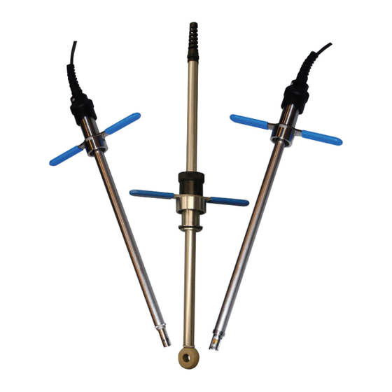
- Page 1 Instruction Model PR10 Manual Retractable Fitting Manual IM 12B06K03-01E-EN-P edition...
-
Page 2: Table Of Contents
Contents 1. PREFACE........................3 1.1 Introduction ......................3 1.2 Unpacking and Checking ..................3 1.3 Warranty and Service ..................... 3 1.4 Serial number ......................4 2. GENERAL SPECIFICATIONS ..................5 2.1 Wetted materials ....................5 2.2 Non-wetted materials ....................5 2.3 Pressure / temperature ratings ................ -
Page 3: Preface
1.2 Unpacking and Checking for return of material, plus the name and phone number of a contact person that When you receive the PR10 retractable can be reached for further information. fitting it is packed in a cardboard box. Open • Clean Statement... -
Page 4: Serial Number
1.4 Serial number The Serial number is defined by nine (9) alphanumeric characters: Production location Year/Month code Tracking number Example: N3P600028 Table 1: Production Year code Table 2: Production Month code Year Year Month Month code Year Year code code January 2014 2026... -
Page 5: General Specifications
2. GENERAL SPECIFICATIONS 2.1 Wetted materials Sensor : For sensor check Instruction Manual Tube and sensor holder : Stainless steel AISI 316L / Titanium O-ring seals : Viton 70° shore 2.2 Non-wetted materials Sensor : For sensor check Instruction Manual Body : Stainless steel AISI 316, 304 : Polypropylene glass filled... -
Page 6: Shipping Details (Configuration Dependant)
2.5 Shipping details (configuration dependant) Fitting Package size (LxWxH) : 760 x 369 x 106 mm (29.9 x 14.5 x 4.1 inch) Package weight (max) : Approx 2.5 kg excl. ball valve (5.5 lbs) Flange Adapter Package size (LxWxH) : 245 x 180 x 210 mm (9.6 x 7.0 x 8.2 inch) Package weight (max) : Approx 2.5 kg excl. -
Page 7: Installation
3.1 General information 3.1.1 Installation site The PR10 fitting is intended to be used for in-line measurement. When it is delivered with an optional ball valve or when it is used in combination with a locally purchased ball valve, the process does not need to be interrupted for maintenance of the sensor. Mounting location can be in a large diameter pipeline or a vessel. -
Page 8: Sensor Installation
3.2 Sensor Installation 3.2.2 Mounting a 12mm PG13.5 sensor in pH13 3.2.1 Mounting a 12mm sensor in pH12 Take the cable out of the box and cut Take the cable out of the box and cut off the cable tie. off the cable tie. -
Page 9: Mounting The Sc4A
3.2.3 Mounting the SC4A metal tube onto the sensor. Don’t rotate the cell, but rotate the tube of the fitting, because the cable can Take the sensor out of the box and cut be disconnected from the cell, when off the cable tie. rotating it. - Page 10 Remarks • Turning the T-bar key can only be done when the valve is closed. • Pushing the probe into the process needs a force to overcome the pressure of the system and the friction of the dampening rings in the fitting. •...
-
Page 11: Maintenance
Follow the procedure described in para- physically separated from the process. The graph 4.3 PR10 retractable fitting can be retracted Dismount the sensor. Follow the procedure from its measuring position in the mainte- described in paragraph 3.2 in reverse... -
Page 12: Dimensions
5. DIMENSIONS 5.1 Dimensional drawing PR10...-D32 with mounted pH sensor Units mm [Inch] PR10-..-..-...-D32-PH.. PR10-..-..-..-D32-PH../F.125/BF125 PR10-..-..-..-D32-PH../F.D32/BFD32 PR10-..-..-..-D32-PH../SA125/BS125 Fig 7: Dimensional drawing PR10...-D32 with mounted pH sensor IM 12B06K03-01E-EN-P... - Page 13 5.2 Dimensional drawing PR10...-D32 with mounted SC4A sensor Units mm [Inch] PR10-..-..-..-D32-SC4A PR10-..-..-..-D32-SC4A/F.125/BF125 PR10-..-..-..-D32-SC4A/F.D32/BFD32 PR10-..-..-..-D32-SC4A/SA125/BS125 Fig 8: Dimensional drawing PR10...-D32 with mounted SC4A sensor IM 12B06K03-01E-EN-P...
- Page 14 5.3 Dimensional drawing PR10...-D32 with mounted FU20 sensor Units mm [Inch] PR10-..-..-...-D32-FU20.. PR10-..-..-..-D32-FU20/FL125/BF125 PR10-..-..-..-D32-FU20/FLD32/BFD32 PR10-..-..-..-D32-FU20/SL125/BS125 Fig 9: Dimensional drawing PR10...-D32 with mounted FU20 sensor IM 12B06K03-01E-EN-P...
- Page 15 5.4 Dimensional drawing PR10...-D50 with mounted pH sensor Units mm [Inch] PR10-..-..-...-D50-PH.. PR10-..-..-..-D50-PH../F.200/BF200 PR10-..-..-..-D50-PH../F.D50/BFD50 PR10-..-..-..-D50-PH../SA200/BS200 Fig 10: Dimensional drawing PR10...-D50 with mounted pH sensor IM 12B06K03-01E-EN-P...
- Page 16 5.5 Dimensional drawing PR10...-D50 with mounted SC4A sensor Units mm [Inch] PR10-..-..-...-D50-SC4A.. PR10-..-..-..-D50-SC4A/F.200/BF200 PR10-..-..-..-D50-SC4A/F.D50/BFD50 PR10-..-..-..-D50-SC4A/SA200/BS200 Fig 11: Dimensional drawing PR10...-D50 with mounted SC4A sensor IM 12B06K03-01E-EN-P...
- Page 17 5.6 Dimensional drawing PR10...-D50 with mounted FU20 sensor Units mm [Inch] PR10-..-..-...-D50-FU20.. PR10-..-..-..-D50-FU20/F.200/BF200 PR10-..-..-..-D50-FU20/F.D50/BFD50 PR10-..-..-..-D50-FU20/SA200/BS200 Fig 12: Dimensional drawing PR10...-D50 with mounted FU20 sensor IM 12B06K03-01E-EN-P...
- Page 18 5.7 Dimensional drawing PR10...-D50 with mounted ISC40 sensor Units mm [Inch] PR10-..-..-..-D50-ISC4 PR10-..-..-..-D50-ISC4/F.200/BF200 PR10-..-..-..-D50-ISC4/F.D50/BFD50 PR10-..-..-..-D50-ISC4/SA200/BS200 Fig 13: Dimensional drawing PR10...-D50 with mounted ISC40 sensor IM 12B06K03-01E-EN-P...
- Page 19 5.8 Dimensional drawing of options Units mm [Inch] Fig 14: Dimensional drawing PR10 options - refer to tabels 4 and 5 on next page IM 12B06K03-01E-EN-P...
- Page 20 Table 4: Dimensions of options - units in mm [inch] IM 12B06K03-01E-EN-P...
- Page 21 Table 5: Dimensions of options - units in mm [inch] IM 12B06K03-01E-EN-P...
-
Page 22: Exploded View
Table 6: Parts and corresponding numbers from exploded view PR10-S-V-L5-D32-PH12 PR10-S-V-L5-D32-PH13 PR10-S-V-L5-D32-SC4A PR10-S-V-L5-D50-ISC4 PR10-S-V-L5-D50-SC4A K1525AG Adapter Y-cap K1525AB Sensor holder PG13.5 SS K1525AP Adapter SC4A - ISC40SS K1525AA Outer tube SS K1525BA O-ring set PR10-S-V-L5-D32 K1525BB O-ring set PR10-S-V-L5-D50 K1525BC Key set K1525BD Squeezing set; IM 12B06K03-01E-EN-P... - Page 23 Fig 16: Exploded view Note: For spare parts see table 6 and table 7 of this chapter and chapter 7 table 8 Table 7: Parts and corresponding numbers from exploded view PR10-T-V-L5-D32-PH12 PR10-T-V-L5-D32-PH13 PR10-T-V-L5-D32-SC4A PR10-T-V-L5-D50-ISC4 PR10-T-V-L5-D50-SC4A K1525AG Adapter Y-cap K1525CB Sensor holder PG13.5 Titanium...
-
Page 24: Model Codes
7. MODEL CODES Table 8: PR10 Model codes Model Suffix Options Description PR10 Retractable fitting general purpose Material fitting -S Stainless steel Titanium (tube and sensor holder only) Material O-rings Viton Tube length Tube length 0.5 meter -D32 DN32 / 1¼”... -
Page 25: Spare Parts
Sensor holder PG13.5 K1525BK Gaskets ball valves - 1¼” Titanium (2x) K1525AP Adapter SC4A-ISC40 SS O-ring sets K1525CP Adapter SC4A-ISC40 K1525BA O-ring set PR10-S-V- Titanium L5-D32 K1525AG Adapter Y-cap K1525BB O-ring set PR10-S-V- L5-D50 K1541EM Adapter 2” NPT - G2 SS K1525KA O-RING SET KALREZ &... -
Page 26: Installation Matrix
9. INSTALLATION MATRIX Table 10: PR10 installation matrix X X X X /SA125 /SL125 X O O O O /SA200 X X X X X X O O O O O /SL200 /FA125 X X X X /FN125 X X X X... - Page 27 Table 11: Combining configurations PR10 X X X X X X X X X X X X X X X X X X X X X X X X X X X X X X X X X X X X X X X...
-
Page 28: Chemical Compatibility Chart
10. CHEMICAL COMPATIBILITY CHART Table 13: Material compatibility table IM 12B06K03-01E-EN-P Printed in The Netherlands, 01-2207 Subject to change without notice Copyright©...
Need help?
Do you have a question about the PR10 and is the answer not in the manual?
Questions and answers