
Related Manuals for YOKOGAWA PH72-21-E-AA


Summary of Contents for YOKOGAWA PH72-21-E-AA
- Page 1 User’s Manual Model PH72 Personal pH/ORP Meter IM 12B03D02-01E IM 12B03D02-01E 3rd Edition...
-
Page 2: Preface
Otherwise battery leakage may occur, causing damage to or malfunction of the meter. The contents of this manual are subject to change without prior notice. Yokogawa Electric Corporation assumes no liability for damage, defects, or loss of the product caused by any of the following: Misuse by the user;... - Page 3 Preface Liquid Crystal Display (LCD) Characters On the LCD alphanumeric characters are displayed as follows. e al Alphabet Alphabet All display segments Note Regarding Panels Shown in this Manual: Panels shown in this manual should be regarded as examples. Actual panel format may vary depending on parameter settings and on type of connected sensor.
- Page 4 Preface Warranty and Service Yokogawa products and parts are guaranteed to be free from defects in workmanship and materials under normal use and service for a period of (typically) 12 months from the date of shipment from the manufacturer. Individual sales units may offer different warranty periods, so the original purchase order should be consulted for the conditions of sale.
-
Page 5: Table Of Contents
Contents CONTENTS Preface ........................1-1 1. Outline ......................... 1-1 1.1 Features ......................... 1-1 1.2 Specifications ......................... 1-2 1.3 When You Receive the PH72 Meter Package .............. 1-3 1.4 PH72 Meter Kit ......................1-4 1.5 PH72 Meter — Part Names and Functions ..............1-5 1.6 Sensors —... - Page 6 Contents 9.3 Temperature Compensation ..................9-4 9.4 The Asymmetry Potential ....................9-5 9.5 The Alkaline Error ......................9-6 9.6 The Acid Error ....................... 9-7 9.7 Calibration Calculation ....................9-8 9.8 ORP (Oxidation-Reduction Potential) ................9-9 9.9 Reference Electrode ....................9-10 9.10 Wetted Part Materials of Sensors ................
- Page 7 Contents IM 12B03D02-01E...
-
Page 8: Outline
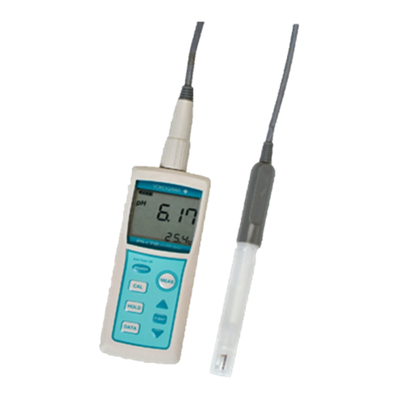
1. Outline 1. Outline The Model PH72 Personal pH/ORP Meter is a highly accurate, portable pH meter for laboratory and field application. With its self-diagnostic function, the PH72 provides precise measurement of pH and ORP (oxidation-reduction potential). Measurement results can be stored and stored data can be checked on the meter display any time. The PH72 meter is of waterproof construction so that it can safely be used outdoors on a rainy day, and can also withstand being accidentally dropped into water. -
Page 9: Specifications
1. Outline 1.2 Specifications Measuring range: 0 to 14 pH* ORP: -2000 to 2000 mV Temperature: 0 to 100 C* Resolution: 0.01 pH ORP: 0.1 mV (-199.9 to 199.9 mV) 1 mV (-2000 to -200 mV and 200 to 2000 mV) Temperature: 0.1 C Repeatability (without sensor):... -
Page 10: When You Receive The Ph72 Meter Package
1. Outline 1.3 When You Receive the PH72 Meter Package Confirm that you received all package components of the PH72 meter you ordered referring to the Model and Suffix Code and the item list in Section 1.4, “PH72 Meter Kit.” Carefully inspect the meter and sensor, referring to Section 1.5, “PH72 Meter — Part Names and Functions”... -
Page 11: Ph72 Meter Kit
1. Outline 1.4 PH72 Meter Kit Item ersona p /OR meter Instrument ard ry batter es, x AA batter es ser s anua and anua Non-s p pads ( p s) and strap Instrument ard rep en sh-free type p sensor ref ab e type p sensor Need e type p sensor est tube s ze p sensor... -
Page 12: Ph72 Meter - Part Names And Functions
1. Outline 1.5 PH72 Meter — Part Names and Functions O r n Sens r cable c nnect r nnect n t a e cate ORP sens r. an stra attac s la an te erat re ltane sl . atter b c er n scre... -
Page 13: Sensors - Types, Part Names And Functions
1. Outline 1.6 Sensors — Types, Part Names and Functions Sensors available for use with the Model PH72 Personal pH/ORP Meter are: general- purpose pH sensors (KCl replenish-free and KCl refillable types), needle type pH sensor, test tube size pH sensor, and KCl refillable type ORP sensor. Check the Model and Suffix Code on the name plate to identify the type of your sensor. - Page 14 1. Outline KCl replenish-free type combination pH sensor KCl refillable type combination pH sensor P sensor PH 2 - 11 - - AA PH 2 - 21 - - AA PH 2 - 1 - - AA PH 2 - 2 - - AA PH 2 - 1 - - AA...
-
Page 15: Options (Available Separately)
1. Outline 1.7 Options (Available Separately) The following options are available for the Model PH72 Personal pH/ORP Meter for your convenience. When ordering, specify the part number. 9 Standard so t on So t arr n Sensor stand (Part no. : K9220X ) (Part no. -
Page 16: Spare Parts
1. Outline 1.8 Spare Parts p 4 tandard so tion tandard so tion p 9 tandard so tion (Part no. : K90 4K ) (Part no. : K90 4K ) (Part no. : K90 4K ) Used or a i ration. ( 50 Used or a i ration. - Page 17 1. Outline O-rings and gaskets are important parts to ensure that the PH72 meter is water resistant. Replace these parts as required. Refer to Section 6.7, “Storage and O-ring/Gasket Replacement” for replacement. 1-10 IM 12B03D02-01E...
-
Page 18: Preparation
2. Preparation 2. Preparation 2.1 Installing the Batteries Install the batteries first. CAUTION Select a relatively moisture-free location when installing batteries in the meter. When installing batteries, observe correct polarity (battery orientation). Failure to do so may damage to the meter. Remove batteries from the meter if it is to be stored for an extended period of time. -
Page 19: Connecting The Sensor Cable
2. Preparation 2.2 Connecting the Sensor Cable Connect the sensor cable. CAUTION Connect the sensor cable in a place free from moisture. When connecting the sensor cable, tighten by turning only the silver locknut, do not turn the cable or waterproof cover. Also take care not wet or contaminate the connector. Sensors for the PH81 or PH82 meters can be connected. -
Page 20: Setting The Date And Time
2. Preparation 2.3 Setting the Date and Time After installing the batteries, set the date and time. Note that if the power is turned off before completing minute setting, start with the date setting when you turn on the power next time. -
Page 21: Selecting Ph Or Orp Measurement
2. Preparation 2.4 Selecting pH or ORP Measurement Upon completing the date and time setting, the meter is ready for pH measurement. The display shows a pH value with a “pH” unit to the left of the value. To use the meter for ORP measurement, make sure that an ORP sensor is connected to the meter. -
Page 22: Manual Temperature Setting
2. Preparation 2.6 Manual Temperature Setting If a sensor without a built-in temperature element (needle type or test tube size pH sensor) is connected to the meter, mark will appear on the display. In this case, measure the temperature of the solution being measured and manually set the measured temperature into the PH72 meter for reliable measurement. - Page 23 2. Preparation IM 12B03D02-01E...
-
Page 24: Measurement
3. Measurement 3. Measurement 3.1 Precautions (1) After storage for an extended period of time, it is recommended that the meter should be calibrated before taking measurements. (2) When using a KCl refillable type sensor, check the level of filling solution. (Refer to Section 6.5.) (3) Do not use the meter in a solution with the temperature exceeding 80 C (100 C for the needle type and test tube size pH sensors). -
Page 25: Measurement Procedures
3. Measurement 3.2 Measurement Procedures Immersing the sensor Immerse the sensor so that the protective cover part goes under the sample solution level. The sensor does not need to be immersed deeply. When using a KCl refillable type sensor, the filling solution level must be above the level of solution being measured. -
Page 26: Measurement Display Panel
3. Measurement 3.3 Measurement Display Panel When immersing the sensor in a sample solution, a measured pH (or mV) value will be shown on the display. There are three types of measurement display panels: the standard, MEAS calendar, and clock display panels. Use key to cycle through these display panels. - Page 27 3. Measurement (2) Data storage If the key is pressed during measurement, mark starts flashing. Press the DATA key, then currently measured data can be stored in nonvolatile memory. Data F/ENT stored are measured conductivity, measured temperature, date and time. Up to 300 data including individually deleted data can be stored.
-
Page 28: Calibration
4. Calibration 4. Calibration Calibration using standard solutions means to measure the pH value of a certified standard solution and to adjust the pH meter so it reads the same value as the certified value of the standard solution. The PH72 meter can be calibrated automatically or manually. - Page 29 4. Calibration Error Messages during Calibration If the meter detects an abnormality during calibration, may be displayed. In such a case take corrective actions referring to Chapter 7, “Troubleshooting.” Canceling Calibration MEAS To cancel the calibration procedure, press key. The meter will return to measurement mode.
-
Page 30: Automatic Calibration
4. Calibration 4.1 Automatic Calibration In automatic calibration the Model PH72 Personal pH/ORP Meter automatically recognizes standard solutions being used and calibrates itself using values of Table 4.1. Two types of standard solutions are preprogrammed: NIST (solutions prepared in accordance with Japanese standards, factory default) and US (solutions prepared in accordance with the U.S. - Page 31 4. Calibration Procedure Example 1: 2-point calibration using pH 7 and pH 4 standard solutions ater ait until rea ing St . sol. stabilizes. as sensor it ater ipe o as ing ater t oroug l (or as in sensor t oroug l ater in bea er).
- Page 32 4. Calibration Example 2: Calibration of a sensor without a built-in temperature element* using a pH 7 standard solution * Needle type or test tube size pH sensor ermometer ater ait until reading stabilizes. Std. sol. as sensor it ater ipe off as ing ater from sensor t oroug l t oroug l...
-
Page 33: Manual Calibration
4. Calibration 4.2 Manual Calibration When using standard solutions other than those preprogrammed for automatic calibration (see Section 4.1), calibration should be performed manually. In 2-point calibration, manual calibration can be performed at both two points or manual calibration performed at one point (either 1st or 2nd) in combination with automatic calibration using a specified standard solution at the other point. - Page 34 4. Calibration Procedure Example 3: Manual calibration cal b a S . s l. s ab l zes. as se s se s bea e . e se se s s lu selec a ual cal b a Ma ual cal b a le e F0403.EPS For 2-pont calibration, continue the procedure following the dotted line.
- Page 35 4. Calibration IM 12B03D02-01E...
-
Page 36: Keypad And Display Functions
5. Keypad and Display Functions 5. Keypad and Display Functions There are eight membrane keys on the keypad of the Model PH72 Personal pH/ORP Meter. The following key functions are provided. • Displaying a pH (or mV) value and temperature •... -
Page 37: Keypad Functions
5. Keypad and Display Functions 5.1 Keypad Functions : Power On/Off key POWER Pressing and holding this key for at least one second when nothing is displayed on the LCD, will turn the meter on. The meter will be turned off by pressing and holding this key for at least two seconds when the meter is on. - Page 38 5. Keypad and Display Functions : Entry key F/ENT Pressing this key during measurement moves the display to function mode. (Refer to Section 5.3, “Function Modes.”) This key is also used to confirm data entry. Beep sound When a key is pressed, the meter acknowledges it using a beep sound. (1) One beep The meter will beep once confirming a valid key entry.
-
Page 39: Display Items
5. Keypad and Display Functions 5.2 Display Items Display items and their descriptions are provided below. Battery condition indicator erat re ettin an a a i ration Sen or c ec F050201.EPS (1) Battery condition indicator Indicates the level of the remaining battery life stepwise. means that there is plenty of life left. -
Page 40: Function Mode
5. Keypad and Display Functions 5.3 Function Mode Outline Various functions are supported by function mode. Press key while the meter is F/ENT in measurement mode to move to function mode. Note: The last selected and executed item is displayed when you move to function mode. - Page 41 5. Keypad and Display Functions Operating procedures on each panel are described below. (1) Display stored data (dAt) panel Shows stored data on the LCD with mark. When you access this panel, the last stored pH (mV) value and temperature will be displayed with the data number flashing at the lower left of the display.
- Page 42 5. Keypad and Display Functions to d s a ot er data a and mont data tem as stored ear data tem as stored Stored measurement data DA A DA A atest data DA A e ete stored data me data tem as stored DA A DA A e ete...
- Page 43 5. Keypad and Display Functions (2) Manual temperature setting (M.tP) panel Used to input the temperature of a solution into the meter when using a sensor without a built-in temperature element (needle type or test tube size pH sensor). This setting is not required when a sensor connected has a built-in temperature element.
- Page 44 5. Keypad and Display Functions (5) Date setting (dAtE) panel Used to set the year (four digits), month and day in this order. Use keys to set the year, month, and day, and press key to confirm each entry. F/ENT Year setting nt setting a setting...
- Page 45 5. Keypad and Display Functions (7) Alarm time setting (ALM) panel Used to enable/disable the alarm clock and set the alarm clock in minutes and seconds. keys to select the desired alarm cycle: 7 days (everyday), 5 days (weekdays) or once. See Item (6), “Time setting (tIME) panel” for setting the time for alarm. The alarm sounds for about 15 seconds.
- Page 46 5. Keypad and Display Functions (8) Set Auto Power Off time (A.oFF) panel Used to set the automatic power off time. The meter turns off power automatically if no key is pressed during this preset time. The time range is from 1 to 120 minutes. If 0 is set, the Auto Power Off function will be disabled.
- Page 47 5. Keypad and Display Functions (11) Initialize calibration parameters (I.CP) panel Used to initialize the parameters saved by calibration to default settings: slope at 1.000 and asymmetry potential at 0.0 mV. F050311.EPS (12) Set temperature unit (tP.U) panel Used to select the temperature unit: Celsius ( C) or Fahrenheit ( F). Use keys to select the desired temperature unit and press key to confirm.
- Page 48 5. Keypad and Display Functions (14) Defrag memory (dFLG) panel Up to 300 data can be stored. Unnecessary data can be individually deleted (refer to Item (1), “Display stored data”), but this individual deletion does not free up memory occupied by deleted data. Therefore, may be displayed even though less than 300 data are stored.
- Page 49 5. Keypad and Display Functions 5-14 IM 12B03D02-01E...
-
Page 50: Maintenance
6. Maintenance 6. Maintenance 6.1 For Optimum Meter Performance The Model PH72 Personal pH/ORP Meter is simple to operate, but is a precision instrument. To ensure accurate results from the meter, the following precautions should be observed. Flow Diagram Measurement rat n Ma ntenan e t ra e... -
Page 51: Ph Electrode Cleaning
6. Maintenance 6.2 pH Electrode Cleaning Dirt or deposits on the glass electrode or liquid junction can often interfere with accurate measurement. Periodical cleaning is required depending on the nature of the solution being measured. CAUTION Do not apply physical shock or excessive force to the glass sensor, or it may break. Do not rub the glass membrane strongly, or it may be damaged or break. -
Page 52: Sensor Replacement
6. Maintenance Af r 10 o 20 0.1 mol/l dil l anin hydrochloric acid Soak in 0.1 mol/l hydrochloric acid horo hly in a r F0602.EPS Figure 6.2 Acid Cleaning 6.3 Sensor Replacement Since a pH sensor undergoes chemical changes with time, its performance deteriorates gradually. -
Page 53: Replenishing The Electrode With Filling Solution (Kcl Solution)
6. Maintenance 6.5 Replenishing the Electrode with Filling Solution (KCl solution) Replenishment is required only when a KCl refillable type combination sensor is used. An electrode filling solution leaks from the liquid junction little by little during measurement. When the level of filling solution drops to the level shown in Figure 6.3, replenish with a 3.3 mol/l KCl solution supplied. -
Page 54: Cleaning And Drying Connectors
6. Maintenance 6.6 Cleaning and Drying Connectors Deteriorated insulation between connector pins can cause inaccurate readings. To remove stains and/or moisture that may cause deteriorated insulation, clean the connector with a dry cloth or a cloth moistened with anhydrous alcohol. If necessary, use a dryer. Wipe off stains and/or moisture on meter connector with a dry cloth. -
Page 55: Storage And O-Ring/Gasket Replacement
6. Maintenance 6.7 Storage and O-ring/Gasket Replacement • Storage Precautions Care is required when storing the meter and sensor. To maintain in good condition, observe the following: (1) Before storage, wash off remaining sample solution from the sensor with water. Deposits on the liquid junction, if any, must be removed thoroughly, or the junction may be clogged. - Page 56 6. Maintenance (1) Replacing the O-ring Install the O-ring on the cylindrical flat part of the connector, as shown below. F060701.EPS (2) Replacing the Gasket Install the gasket on the groove on the battery box so the raised part fits in place as shown below.
- Page 57 6. Maintenance IM 12B03D02-01E...
-
Page 58: Troubleshooting
(1) Improper maintenance or usage (2) Expired consumables (3) Failure If any trouble occurs, determine the cause and take corrective actions referring to Section 7.2. If the trouble cannot be fixed, contact your nearest Yokogawa sales office. Unstable reading Abnormal reading rror message... -
Page 59: Error Messages, Possible Causes, And Corrective Actions
7. Troubleshooting 7.2 Error Messages, Possible Causes, and Corrective Actions Table 7.1 Error Message Error Message* es r Unstable input emf Abno mal asymmet y potential u ing calib ation Abno mal slope o calib ation tempe atu e Out of measu ing ange Out of tempe atu e measu ing ange u ing measu ement Mete elect onics failu e... - Page 60 7. Troubleshooting (2) Err2 Abnormal asymmetry potential Appears during calibration. A sensor deteriorates in service and the emf deviates from the initial one. If the difference increases and exceeds the limit that can be compensated by calibration, an Err2 message will appear. It will also appear if the pH value of the standard solution is abnormal or if the asymmetry potential is outside the range of -96 to 120 mV.
- Page 61 7. Troubleshooting (3) Err3 Abnormal slope or calibration temperature Appears during calibration. In the Model PH72 Personal pH/ORP Meter standard solution data (NIST and US) are preprogrammed. During automatic calibration the meter recognizes standard solutions being used based on these data. If standard solutions other than the preprogrammed ones are used, an Err3 message will appear.
-
Page 62: Causes Of Abnormal Measured Values
Possible Cause: • Failure of electronics. Corrective Action: • Contact your nearest Yokogawa sales office. 7.3 Causes of Abnormal Measured Values If error messages do not occur, but measured values seem incorrect, check the following: • Are proper standard solutions used? •... -
Page 63: Other Conditions
7. Troubleshooting 7.4 Other Conditions • An alarm sounds The alarm is set to sound at the preset alarm time. Refer to Section 5.3 (7), “Alarm time setting (ALM) panel.” • Beeps The beep sound to acknowledge a key press can be enabled/disabled. Refer to Section 5.3 (9), “Set beep on/off (bZ.o) panel.”... -
Page 64: Orp Meter
8. ORP Meter 8. ORP Meter 8.1 ORP Measurement Use a dedicated ORP sensor for ORP (oxidation-reduction potential) measurement. The ORP sensor is a KCl refillable type with a platinum sensing electrode and looks the same as a KCl refillable type pH sensor. The measuring temperature range of the ORP sensor is 0 to 80 C, the same as that of the pH sensor. -
Page 65: Maintenance Of Orp Sensors
8. ORP Meter 8.2 Maintenance of ORP Sensors Maintenance of ORP sensors is in accordance with that of pH sensors. (Refer to Chapter 6, “Maintenance.”) Cleaning the Platinum Electrode and Liquid Junction Dirt or deposits on the platinum electrode or liquid junction may interfere with accurate measurement. -
Page 66: Checking The Orp Sensor
8. ORP Meter 8.3 Checking the ORP Sensor Use a check solution to verify that the ORP sensor operates properly. The oxidation- reduction potential of the check solution to be used should have been correctly determined by a normal ORP sensor. The following explains how to check an ORP sensor using a quinhydrone reagent (spare part). - Page 67 8. ORP Meter T era Temperature ( Figure 8.2 Oxidation-Reduction Potential of Check Solution IM 12B03D02-01E...
-
Page 68: Technical Information
9. Technical Information 9. Technical Information 9.1 Measurement Principle of pH Meter (Glass Electrode Method) A pH meter makes use of the potential difference developed between the two sides of a thin glass membrane that separates two solutions with different pH. Figure 9.1 shows the schematic diagram of the measurement principle. -
Page 69: Relationship Between Emf Of Glass Membrane And Ph Value
9. Technical Information 9.2 Relationship between EMF of Glass Membrane and pH Value The relationship between the potential difference (electromotive force) developed across the glass membrane and the pH value had been studied and the theoretical values were determined. Actual values, however, do not match the theoretical values due to manufacturing variations or deterioration with time. - Page 70 9. Technical Information oundar la ers Internal solution side le solution side drated la ers on lass F0902.EP Figure 9.2 Diagram of Glass Membrane -100 - 00 - 00 Alkaline error -400 - 00 F090 . PS Figure 9.3 Relationship between Glass Electrode Potential and pH IM 12B03D02-01E...
-
Page 71: Temperature Compensation
9. Technical Information 9.3 Temperature Compensation In equation 9.3, 2.3026RT/F represents the emf per pH unit and varies depending on temperature. Table 9.1 EMF per pH (values of 2.3026RT/F) 2.3026 T 2.3026 T 2.3026 T Temperature Temperature Temperature 54.20 61.14 68.09 55.19 62.14... -
Page 72: The Asymmetry Potential
9. Technical Information Table 9.2 Deviations from True Values in Measurement without Temperature Compensation -0.70 -1.11 0.50 0.10 0.00 -0.30 0.00 -0. 0 -0.47 -0.74 0.34 0.07 0.00 -0.10 -0. 3 -0.37 0.17 0.03 0.00 0.00 0.00 0.00 0.00 0.00 -0.17 -0.03 0.00... -
Page 73: The Alkaline Error
9. Technical Information 9.5 The Alkaline Error As shown in Figure 9.5, the emf of a glass electrode deviates from the linear value on the alkaline side. This is called the alkaline error. The magnitude of the alkaline error varies depending on the glass membrane compositions. The alkaline error is likely to occur with the presence of sodium and lithium and even with the same pH, it varies depending on the types and concentrations of cations and on the temperature. -
Page 74: The Acid Error
9. Technical Information ra r 0 1m Figure 9.7 Ion Concentration vs Alkaline Error 9.6 The Acid Error The acid error also varies depending on the glass membrane compositions and the types of acids. It increases gradually with immersion time and finally reaches equilibrium. Once a glass electrode has the acid error, it cannot recover soon even by being soaked in a neutral solution and needs considerable time. -
Page 75: Calibration Calculation
9. Technical Information 9.7 Calibration Calculation The PH72 meter is calibrated at 2 points using 2 standard solutions. The first calibration is done so a certain line is drawn through the calibration point (Figure 9.9). The second calibration is done so a line is drawn through the first and second calibration points (Figure 9.10). -
Page 76: Orp (Oxidation-Reduction Potential)
9. Technical Information 9.8 ORP (Oxidation-Reduction Potential) In general, oxidation is the gain of oxygen or the loss of hydrogen, and reduction is the loss of oxygen or the gain of hydrogen. In the electrochemistry field, oxidation is defined as the loss of electrons and reduction is defined as the gain of electrons. These reactions are reversible and expressed as follows: –... -
Page 77: Reference Electrode
In the electrochemical field, the hydrogen electrode is generally used as a reference electrode. However, it has complicated construction and is impractical. Therefore, in Yokogawa's ORP sensors, an Ag/AgCl electrode filled with a 3.3 mol/l KCl solution is used as a reference electrode. - Page 78 9. Technical Information Obtained from equation 9.10, the potential of the Ag/AgCl electrode filled with a 3.3 mol/l KCl solution, E' , has the temperature characteristic for the standard hydrogen AgCl electrode as shown in Figure 9.12. To convert E' to the value for the standard hydrogen electrode, AgCl (9.11)
-
Page 79: Wetted Part Materials Of Sensors
9. Technical Information 9.10 Wetted Part Materials of Sensors • General pH Sensors Polypropylene resin (sensor body, protective cover) Glass (glass electrode, temperature element protective tube) Ceramics (liquid junction) Silicon rubber (sensor seal) - When cable is immersed (KCl replenish-free type) Rigid polyethylene (sensor grip) PVC (sensor cable) Ethylene propylene rubber (sensor grip, cable connection) -
Page 80: Appendix
Appendix Appendix Key-Operation Flow Chart (for reference) Typical screens are shown. Refer to the corresponding section in the body of the manual for details. le displa t pe First time used, or M AS after replace batteries M AS M AS M AS da a M AS... - Page 81 Appendix D splay s DA A DA A DA A DA A T02.EPS IM 12B03D02-01E...
- Page 82 Appendix all s r Alar as r s a s as r as r s a s M AS T03.EPS IM 12B03D02-01E...
- Page 83 Appendix al z al ra ar s l ra r aram rag m m r T04.EPS IM 12B03D02-01E...
- Page 84 Appendix Calibration Auto atic calibration Manual calibration 2 oint calibration A to calibration A to calibration in rogr Auto calibration i co Manual calibration ting an al calibration i co Auto atic calibration for needle type or test tube size pH sensor Auto calibration rat r 25.0 C i...
- Page 85 Appendix IM 12B03D02-01E...
- Page 86 MSDS MSDS (Material Safety Data Sheet) The contents are provided for informative purposes only and no guarantee is given to the accuracy. The information, such as manufacturers, in the data sheets is subject to change without notice. Item MSDS Product Name Page Standard pH4 standard solution Phthalate standard solution...
-
Page 87: Msds (Material Safety Data Sheet)
MSDS MSDS-2 IM 12B03D02-01E... - Page 88 MSDS MSDS-3 IM 12B03D02-01E...
- Page 89 MSDS MSDS-4 IM 12B03D02-01E...
- Page 90 MSDS MSDS-5 IM 12B03D02-01E...
- Page 91 MSDS MSDS-6 IM 12B03D02-01E...
- Page 92 MSDS MSDS-7 IM 12B03D02-01E...
- Page 93 MSDS MSDS-8 IM 12B03D02-01E...
- Page 94 MSDS MSDS-9 IM 12B03D02-01E...
- Page 95 MSDS MSDS-10 IM 12B03D02-01E...
- Page 96 MSDS MSDS-11 IM 12B03D02-01E...
- Page 97 MSDS MSDS-12 IM 12B03D02-01E...
- Page 98 MSDS MSDS-13 IM 12B03D02-01E...
- Page 99 MSDS MSDS-14 IM 12B03D02-01E...
- Page 100 MSDS MSDS-15 IM 12B03D02-01E...
- Page 101 MSDS MSDS-16 IM 12B03D02-01E...
- Page 102 MSDS MSDS-17 IM 12B03D02-01E...
- Page 103 MSDS MSDS-18 IM 12B03D02-01E...
- Page 104 MSDS MSDS-19 IM 12B03D02-01E...
- Page 105 MSDS MSDS-20 IM 12B03D02-01E...
- Page 106 MSDS MSDS-21 IM 12B03D02-01E...
- Page 107 MSDS MSDS-22 IM 12B03D02-01E...
-
Page 108: Revision Record
Revision Record Manual Title : Model PH72 Personal pH/ORP Meter Manual Number : IM 12B03D02-01E Edition Date Remark (s) Oct. 2004 Newly published Apr. 2008 Addition of information on EMC compliance: P.1-2 Addition of CAUTION: P2-2 Correction: P.1, 1-2, 1-6, 2-1, 2-5, 3-1, 5-4, 6-1, 7-6, 8-3, 9-4, 9-6, 9-7 Apr. - Page 109 Do not dispose in domestic household waste. When disposing products in the EU, contact your local Yokogawa Europe B. V. office. • Authorized Representative in EEA The Authorized Representative for this product in EEA is Yokogawa Europe B.V. (Euroweg 2, 3825 HD Amersfoort, The Netherlands). IM 12B03D02-01E ©...
- Page 110 Preface Warranty and Service Yokogawa products and parts are guaranteed to be free from defects in workmanship and materials under normal use and service for a period of (typically) 12 months from the date of shipment from the manufacturer. Individual sales units may offer different warranty periods, so the original purchase order should be consulted for the conditions of sale.
- Page 111 1. Outline PH72 Meter Kit Item Personal pH/ORP meter User's Manual and Quick Manual Non-slip pads (2 pcs) Hand strap Dry batteries, 2x AA batteries KCl replenish-free type pH sensor KCl refillable type pH sensor Needle type pH sensor Test tube size pH sensor KCl refillable type ORP sensor Cotton swabs for sensor cleaning Quick Manual...
- Page 112 1. Outline Options (Available Separately) The following options are available for the Model PH72 Personal pH/ORP Meter for your convenience. When ordering, specify the part number. pH 9 Standard solution (Part no. : K9220XF) Used for calibration when anticipated pH value of sample solution is alkaline (50mL).
Need help?
Do you have a question about the PH72-21-E-AA and is the answer not in the manual?
Questions and answers