Table of Contents
Advertisement
Quick Links
Advertisement
Table of Contents

Related Manuals for Audio Authority Access EZ 955


Summary of Contents for Audio Authority Access EZ 955
- Page 1 Demonstration Network Home Audio and Video System Installation Manual...
-
Page 3: Table Of Contents
The words “Audio Authority” in any font, the Audio Authority logo, and the “double-A” symbol, are registered trademarks of Audio Authority Corporation. Access Demonstration Network, AccessEZ, AutoDamping, SPL Auto Limiting, TheftAlert, AccessEZ and SilenTouch are trademarks of Audio Authority Corporation. -
Page 4: Orientation
ORIENTATION This manual is provided as a framework to help you successfully install your Access System, test its operation, and then use the system to demonstrate and sell your merchandise. This • Tips • Examples manual covers the proper installation of the switching system hardware only. If your system •... -
Page 5: How The Access ™ System Works
*A touchscreen interface requires custom software that may be created by the user or by Audio Authority. Custom software charges apply. -
Page 6: Access ™ System Components
Each button has a four-conductor (or two-conductor) cable connecting the button to the switch module (See page 25 if using two-conductor buttons.) Audio Authority carries several button styles and colors, check with your Account Manager for colors and availability. - Page 7 System Module Model 980B System Control Module System Module performs vital tasks within the Access System such as SilenTouch , speaker limit, and provides ™ ™ an interface for a 903 Control Panel. One per system. Special Modules and Devices These modules provide extra capabilities, and are not required for many systems.
-
Page 8: Single Product Group Switching System
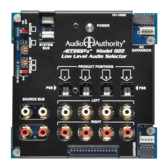
Receiver, Amplifier and Soundbar Modules Model 942 Amplifier Selector Module Model 942 controls four two-channel amplifiers or receivers. One module accommodates both low-level inputs and high-level outputs. For high current amplifier applications, use 922 for input, but dock a heavy duty 949X module to it to switch the high current speaker output signals (See also 939 below.) Model 945 Receiver Selector Module Model 945 controls four Surround Sound or Digital Audio receivers. - Page 9 Audio Sources Use a 922 Low-Level module for every four CD players, music servers, or satellite radio receivers you plan to include in your switching system (Figure 10). Connect each source to a 922, and connect the system bus and low-level bus from the 922 module to the “Bus In”...
-
Page 10: Multi-Component 2-Channel Switching
Stereo Receivers Use one 942 module for the input/output for every four stereo receivers (not shown). The low-level bus connects the dedicated source to the 980 module, and from there it links all the 942 modules in the receiver group. Connect all main modules with system bus and speaker bus (for more detail, find “bus cable installation”... - Page 11 List the Switching Modules Figure 15 shows the modules needed to switch each type of product in this example display. Each electronics module supports four products, and each speaker module supports eight speakers. To switch eight speaker pairs, use one 932 module for the right, and one for the left. The Access System’s architecture was designed for up to sixteen unique speaker groups, with a capacity within each group for 99 pairs of speakers.
-
Page 12: Home Theater Switching System
Video Signals For demonstrating multiple video displays or projectors using HDMI, use our HDMI distribution amplifiers. If your merchandising plan requires HDMI video switching, Audio Authority can provide a customized 970A-1 to interface with an HDMI switch. See audioauthority.com/hdmi-demo for details. - Page 13 Subwoofer Switching Options Powered subs can be wired low-level in systems where all receivers have a low-level “Sub Out” jack, or they can be wired high-level, tapping into the full range signal for the front speakers. Call Audio Authority for more ®...
-
Page 14: Video Distribution System
ADDING CONTROL INTERFACES One Interface or a Combination of Interfaces Your system may be operated by PSBs alone, or you can use a control panel, or both. Your Audio Authority Account ®... -
Page 15: Preparation
INSTALLATION 1. Preparation Follow these steps carefully: • Review the design of the demonstration area, and make sure the display shelving is correct for your installation. • Look at the supplied system wiring diagram, or choose one from this manual to serve as an example. Examples are in Appendix A: Sample Systems. - Page 16 Speaker Groups The Access System allows a ™ maximum of 16 unique speaker groups, with a capacity within each group for 99 pairs of speakers. Some of the unique speaker group possibilities are: • Front Speakers • Center Speakers • Rear Speakers •...
- Page 17 C. Set the Address Switches. Remember, begin with Group 0/ 00 for the first module in the Source Group, and the next module is 0/01. If the Receiver Product Group is next, the first 945 module will have an address setting of 4/00 (Figure 26), so the first module in the Front Speaker Product Group would be 4/00 as well (Figure 27).
-
Page 18: Install The System Hardware
• Follow your system plan design to determine the location of the switching modules in the display fixture. If you are using bus cables provided by Audio Authority , you may wish to connect all the modules that share ®... - Page 19 A. Install the System Bus The System Bus allows all of the Access components to communicate among ™ themselves, and with the control panel. You may use either header in the location YELLOW WIRE labeled System Bus. Do not connect System Bus to any expander modules such as the ALWAYS ON 920X, or 940X.
- Page 20 Y adapters applied only to the inputs of each stereo subwoofer. D. HDMI Video Distribution The Audio Authority Distribution Amplifiers are easy to install. Some other rules are as follows: • Each distribution amp should be permanently mounted as close as possible to the products it feeds, and within reach of an AC power outlet.
-
Page 21: Check Your Work To This Point
5. Check your work to this point Before continuing any further, double check the following: • Check the Group and Module ID settings on all modules. Your Group numbers TECH TIPS should follow a similar pattern to the example in Figure 34. Make sure the Module ID settings are in consecutive order in each Product Group, beginning with zero, not skipping any numbers. - Page 22 Model 903 Control Panel Model 906G Control Panel Custom Third-Party Touchscreen Product Select Buttons...
-
Page 23: Installing A Control Method
INSTALLING A CONTROL METHOD 1. Installing a Control Panel Skip this step if you do not have a 903 or 906G Control Panel. If you have a 903 Control Panel, it is accompanied by a separate User’s Guide which you should locate for future reference. Note: The 903 Control Panel can also be remotely controlled using a third party IR remote programmed with the IR codes available at audioauthority.com/access_tips. -
Page 24: Switch Settings
Switch Settings Switch Function Comments Keyboard Click Turn ON for audible key feedback or “beep” Demo-Mode Leave OFF. Use only when control panel is not connected to a system as a “Training Mode” Systems ON makes the last (unused) Product Group capable of Memory storing and recalling 99 system configurations (see 903 manual) Future Use... -
Page 25: Installing Remote Switches
C. Locate the switching module where the component will be connected. Each module has either 2-pin or 4-pin headers above the product connectors numbered from 1-4, or 1-8 (Figure 39). As you install the display products, you will connect the PSBs to these headers using the cable assembly supplied with each, being careful to observe proper polarity (Figure 40). -
Page 26: Testing System Function
If “bUS” disappears from the Info Display, you have isolated the module or bus cable that is faulty. Re-address the module and cycle power or replace the cable. d. Call Audio Authority Technical Service at 800-322-8346 for assistance with parts replacement. - Page 27 4. After the bus test, the diagnostic program scans the active range of module addresses in every Product Group. You will observe these module addresses counting up in the Info Display as the product group number is displayed in each group’s Product Group window. Lowest group numbers first, and electronics groups come up before speaker groups (e.g., 922, 945, 955, 956, (all electronics), 932, 939, (speakers).
- Page 28 3. Testing the Product Positions Use the PSBs (product select buttons) to select each position called for in the following procedures. If your system does not include PSBs, use a screwdriver to short one set of the two outside pins of the small 4-pin PSB port at each location as shown in Figure 46 and called for in the following steps.
-
Page 29: Demo Product Installation
DEMO PRODUCT INSTALLATION It is now time to begin installing the audio-video components. If you’ve followed the instructions so far, you will have a working system in short order. It may be a good idea to map out a wiring plan for the audio and video components before you begin connecting them to the switching system and to AC power. - Page 30 Follow the signal path visually through the product hookups and system buses to make sure there are no wiring errors or RCA cables that have been pulled loose. If you still have difficulty, call Audio Authority Technical Support at 800-322-8346.
-
Page 31: User Tips
4. Test All Products This section covers operation of Access Systems using PSBs rather than a Control Panel. For operation of systems ™ utilizing a control panel, please see the separate User’s Guide included with the control panel. 1. Make sure the system is on (check power lights on switch modules.) 2. -
Page 33: Reference
REFERENCE Appendix A: Sample Systems Multi-Product Group Systems Stereo System with 903 Control Panel Home Theater System with 903 Control Panel Single Product Group Systems A-V Source System with 906G Control Panel Home Theater Speaker Package System with 906G Control Panel Soundbar Demonstration System with 906G Control Panel Soundbar and A-V Receiver Demonstration System with 906G Control Panel Appendix B: Product Connection Diagrams... -
Page 34: Appendix A: Sample Systems
Speaker Bus 4/00 L 4/00 R Left Right Speakers Speakers Speaker Bus System Bus Audio Authority Tech Support USA and Canada: 800-322-8346 (Mon-Fri 8:30 AM to 5:00 PM Eastern Time) Phone: 859-233-4599 Fax: 859-233-4510 Hookup drawings and FAQ audioauthority.com/access_tips TECH TIPS... - Page 35 Left Rear Right Rear Ceiling Ceiling Speakers Speakers 9/00 L 9/00 R Rear Ceiling Audio Authority Tech Support USA and Canada: 800-322-8346 (Mon-Fri 8:30 AM to 5:00 PM Eastern Time) Phone: 859-233-4599 Fax: 859-233-4510 Hookup drawings and FAQ audioauthority.com/access_tips TECH TIPS...
- Page 36 Rear Channel Channel Digital Surround Subwoofer Sound Receiver 920X Center Channel Subwoofer Bus Audio Authority Tech Support USA and Canada: 800-322-8346 (Mon-Fri 8:30 AM to 5:00 PM Eastern Time) Phone: 859-233-4599 Fax: 859-233-4510 Hookup drawings and FAQ audioauthority.com/access_tips TECH TIPS...
- Page 37 Audio Authority for more options. Digital Surround Soundbar Sound Receiver Audio Authority Tech Support USA and Canada: 800-322-8346 (Mon-Fri 8:30 AM to 5:00 PM Eastern Time) Hookup drawings and FAQ audioauthority.com/access_tips Phone: 859-233-4599 Fax: 859-233-4510 TECH TIPS...
-
Page 38: Appendix B: Product Connection Diagrams
Composite Video Bus Connections Signal Expander Port Model 955 A-V Source Selector Composite Video Audio Authority Tech Support USA and Canada: 800-322-8346 (Mon-Fri 8:30 AM to 5:00 PM Eastern Time) Hookup drawings and FAQ audioauthority.com/access_tips Phone: 859-233-4599 Fax: 859-233-4510 TECH TIPS... - Page 39 Signal Expander Port *2-wire or 4-wire PSBs may be used. See page 25 for more information Audio Authority Tech Support USA and Canada: 800-322-8346 (Mon-Fri 8:30 AM to 5:00 PM Eastern Time) Phone: 859-233-4599 Fax: 859-233-4510 Hookup drawings and FAQ audioauthority.com/access_tips...
- Page 40 Output to EXPAND DAC Input Optical Left/Right Audio Input Left/Right Bus Audio Output Audio Authority Tech Support USA and Canada: 800-322-8346 (Mon-Fri 8:30 AM to 5:00 PM Eastern Time) Phone: 859-233-4599 Fax: 859-233-4510 Hookup drawings and FAQ audioauthority.com/access_tips TECH TIPS...
- Page 41 From Audio Source (Low-Level Out) or Processor (Front Low-Level Out) To Receiver Product Group Audio Authority Tech Support USA and Canada: 800-322-8346 (Mon-Fri 8:30 AM to 5:00 PM Eastern Time) Phone: 859-233-4599 Fax: 859-233-4510 Hookup drawings and FAQ audioauthority.com/access_tips TECH TIPS...
- Page 42 See page 25 for more information Wire Color Code Green L+ Brown R+ White L– Gray R– Audio Authority Tech Support USA and Canada: 800-322-8346 (Mon-Fri 8:30 AM to 5:00 PM Eastern Time) Phone: 859-233-4599 Fax: 859-233-4510 Hookup drawings and FAQ audioauthority.com/access_tips TECH TIPS...
- Page 43 945 module via See page 25 for more information Model 980 connects here Audio Authority Tech Support USA and Canada: 800-322-8346 (Mon-Fri 8:30 AM to 5:00 PM Eastern Time) Phone: 859-233-4599 Fax: 859-233-4510 Hookup drawings and FAQ audioauthority.com/access_tips TECH TIPS...
- Page 44 This diagram shows connections to receivers with analog audio outputs, digital audio inputs, and a low-level sub out jack. If a receiver does not have some of the features shown, simply leave those jacks or terminals vacant on the 945. Instructions for other types of surround sound configurations are available if needed. Contact your Audio Authority ®...
- Page 45 See page 25 for more information Green L+ Brown R+ White L– Gray R– Audio Authority Tech Support USA and Canada: 800-322-8346 (Mon-Fri 8:30 AM to 5:00 PM Eastern Time) Phone: 859-233-4599 Fax: 859-233-4510 Hookup drawings and FAQ audioauthority.com/access_tips TECH TIPS...
-
Page 46: Definition Of Terms
Definition of Terms To successfully install your new Access Demonstration Network, you should familiarize yourself with the following terms: Address A number that pinpoints the identity and location of a switch module within that system. The installer sets numeric switches like the ones in Figure 26 on page 17 for each module that provides a unique address in the proper sequence for each component connected to the system. - Page 47 Module A basic component of the Access System. There are five types of modules normally ™ found in home entertainment applications: Switching Modules or Product Selector Modules select and connect products • for demonstration and communicate with other system components through the System Bus.
-
Page 48: Access™ Warranty
Out of Warranty Service Audio Authority® products that fail after the warranty period has expired may be returned to the factory for repair at a nominal charge, if not damaged beyond the point of repair. Most Audio Authority products may be repaired by the factory at our current, published Service Fee. -
Page 49: Index
Index Control panel cut-out sizes…23 Control Panel, definition of…46 Control Panel installation…23 Model 980 4-Channel hookup…41 Product Numbers Control Panel testing…26 Module count on 903…27 Control Panel to select products…6 Module, definition of…47 903 Control Panel in example wiring Control Panels…6 Module ID and address diagram…34 settings…15... - Page 50 Sample wiring diagram…34 Selecting Products…5 Signal Buses, different types…5 SilenTouch, definition of…47 SilenTouch LED and normal operation…26 Software version…26 Source Bus installation…20 Source selector…7 Speaker Bus…19. See also Speaker Bus Installation Speaker Bus example wiring diagram…11 Speaker Bus installation…19 Speaker extension…19 Speaker Hookup…45 Speaker Limit…28 Speaker Limit settings…31...
- Page 52 2048 Mercer Road, Lexington, Kentucky 40511-1071 800-322-8346 • 859-233-4599 • Fax: 859-233-4510 www.audioauthority.com • support@audioauthority.com • Tips • Examples 752-148B • FAQ 20151216 audioauthority.com/access_tips...
Need help?
Do you have a question about the Access EZ 955 and is the answer not in the manual?
Questions and answers