Table of Contents
Advertisement
INSTALLATION
MANUAL
CEILING CASSETTE
R410A SPLIT TYPE AIR CONDITIONER
(E Series)
MODELS
FCRN50EXV1
FCRN60EXV1
FCRN71EXV1
FCRN100EXV1
FCRN125EXV1
FCQN50EXV1
FCQN60EXV1
FCQN71EXV1
FCQN100EXV1
FCQN125EXV1
CVR 5CKE-0912(0)DAIKIN-EN.indd 1
CVR 5CKE-0912(0)DAIKIN-EN.indd 1
RN50C(G)XV1
RN60C(G)XV1
RR71C(G)XV1
RR90D(G)XV1
RR90D(G)XY1
RR100D(G)XV1
RR100D(G)XY1
RR125D(G)XY1
RYN50C(G)XV1
RYN60C(G)XV1
RQ71C(G)XV1
RQ90D(G)XV1
RQ90D(G)XY1
RQ100D(G)XV1
RQ100D(G)XY1
RQ125D(G)XY1
Installation Manual
R410A Split Type Air Conditioner
Manuel D'installation
Climatiseurs Split System R410A
Installationshandbuch
Doppelfunktions-Klimagerät and R410A
Manuale Di Installazione
Condizionatore Split A R410A
Manual De Instalación
Equipo de air Acondicionado de tipo
Dividido de R410A
Руководство по установке
R410A разделить Кондиционер
воздуха типа
Kurulum kılavuzu
R410A Split Tipi Klima
IM-5CKE-0912(0)DAIKIN
Part No.: R08019038169
English
Français
Deutsch
Italiano
Español
Русский
Türkçe
9/27/12 12:12:39 PM
9/27/12 12:12:39 PM
Advertisement
Table of Contents

Related Manuals for Daikin FCRN50EXV1


Summary of Contents for Daikin FCRN50EXV1
- Page 1 воздуха типа RR100D(G)XV1 FCQN50EXV1 RR100D(G)XY1 Kurulum kılavuzu Türkçe R410A Split Tipi Klima FCQN60EXV1 RR125D(G)XY1 FCQN71EXV1 FCQN100EXV1 RYN50C(G)XV1 FCQN125EXV1 RYN60C(G)XV1 RQ71C(G)XV1 RQ90D(G)XV1 RQ90D(G)XY1 RQ100D(G)XV1 RQ100D(G)XY1 IM-5CKE-0912(0)DAIKIN RQ125D(G)XY1 Part No.: R08019038169 CVR 5CKE-0912(0)DAIKIN-EN.indd 1 CVR 5CKE-0912(0)DAIKIN-EN.indd 1 9/27/12 12:12:39 PM 9/27/12 12:12:39 PM...
-
Page 2: Outline And Dimensions
OUTLINE AND DIMENSIONS Indoor Unit (FCRN/FCQN) All dimensions are in mm Dimension Model 50/60/71E 100/125E Outdoor Unit (RN/RR/RYN/RQ) All dimensions are in mm Dimension Model 60/71C Dimension Model 60/71C 1 IM-5CKE-0912(0)DAIKIN-EN.indd 1 1 IM-5CKE-0912(0)DAIKIN-EN.indd 1 9/28/12 2:04:14 PM 9/28/12 2:04:14 PM... - Page 3 Outdoor Unit (RR/RQ) All dimensions are in mm MADE IN MALAYSIA Dimension Model 90/100/125D 1030 826 400 410 746 142 1 IM-5CKE-0912(0)DAIKIN-EN.indd 2 1 IM-5CKE-0912(0)DAIKIN-EN.indd 2 9/28/12 2:04:14 PM 9/28/12 2:04:14 PM...
-
Page 4: Safety Precautions
Please contact the installer or local authority for more information. Batteries must be removed from the remote controller and disposed of separately in accordance with relevant local and national legislation. 1 IM-5CKE-0912(0)DAIKIN-EN.indd 3 1 IM-5CKE-0912(0)DAIKIN-EN.indd 3 9/28/12 2:04:14 PM... - Page 5 Periodical inspections for refrigerant leaks may be required depending on European or local legislation. Please contact your local dealer for more information. * on the outdoor unit 1 IM-5CKE-0912(0)DAIKIN-EN.indd 4 1 IM-5CKE-0912(0)DAIKIN-EN.indd 4 9/28/12 2:04:15 PM 9/28/12 2:04:15 PM...
-
Page 6: Installation Diagram
Do not move the unit from packaging while moving, until it reaches the installation site. Use safe material or protection plates when unpacking it or lifting it to avoid damage or scratches to the unit. 0.5m or more 0.5m or more 0.5m or more Obstacle Floor 1 IM-5CKE-0912(0)DAIKIN-EN.indd 5 1 IM-5CKE-0912(0)DAIKIN-EN.indd 5 9/28/12 2:04:15 PM 9/28/12 2:04:15 PM... -
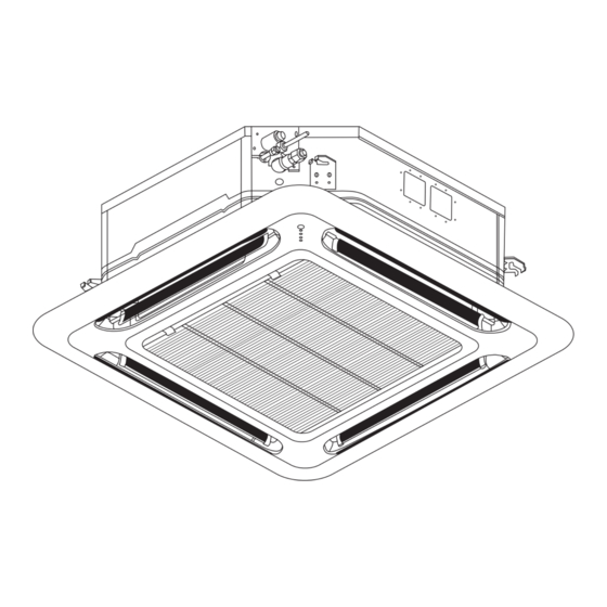
Page 7: Unit Installation
Indoor Unit falling and vibration. Ceiling • Open the ceiling board along the outer edge of the paper Board installation template. 30 mm 1 IM-5CKE-0912(0)DAIKIN-EN.indd 6 1 IM-5CKE-0912(0)DAIKIN-EN.indd 6 9/28/12 4:27:24 PM 9/28/12 4:27:24 PM... -
Page 8: Drain Piping Work
Connect the LED wire and air swing wire to the indoor unit. • The air swing connector must put inside the control box after connected. LED Wire From Front From Unit Panel Control Box Air Swing Wire 1 IM-5CKE-0912(0)DAIKIN-EN.indd 7 1 IM-5CKE-0912(0)DAIKIN-EN.indd 7 9/28/12 2:04:16 PM 9/28/12 2:04:16 PM... - Page 9 Remove the cover lock grille and open the intake grille for the service purpose. Install the intake grille and screw the cover lock grille after service and make sure the unit is proper install. 1 IM-5CKE-0912(0)DAIKIN-EN.indd 8 1 IM-5CKE-0912(0)DAIKIN-EN.indd 8...
- Page 10 Wires will go through the hole as shown in Figure D and E respectively without crossing the height of the hole. After that, wire cover will be assembled back to close the wire. Figure B Figure C Figure D Figure E 1 IM-5CKE-0912(0)DAIKIN-EN.indd 9 1 IM-5CKE-0912(0)DAIKIN-EN.indd 9 9/28/12 2:04:17 PM 9/28/12 2:04:17 PM...
- Page 11 The location must not be susceptible to dust or oil mist. ! CAUTION • Do not install the unit at altitude over 2000m for both indoor and outdoor. 1-10 1 IM-5CKE-0912(0)DAIKIN-EN.indd 10 1 IM-5CKE-0912(0)DAIKIN-EN.indd 10 9/28/12 2:04:17 PM 9/28/12 2:04:17 PM...
-
Page 12: Installation Clearance
Be sure to add the proper amount of additional refrigerant, failure to do so may result in reduced performance. Remark: The refrigerant pre-charged in the outdoor unit is for the piping length up to 7.5m. 1-11 1 IM-5CKE-0912(0)DAIKIN-EN.indd 11 1 IM-5CKE-0912(0)DAIKIN-EN.indd 11 9/28/12 2:04:17 PM... - Page 13 78 (57.6) Ø Tube, D A (mm) Imperial Rigid Inch (Wing-nut Type) (Clutch Type) 1/4" 6.35 3/8" 9.52 1/2" 12.70 5/8" 15.88 Torque Wrench Spanar 3/4" 19.05 1-12 1 IM-5CKE-0912(0)DAIKIN-EN.indd 12 1 IM-5CKE-0912(0)DAIKIN-EN.indd 12 9/28/12 2:04:18 PM 9/28/12 2:04:18 PM...
-
Page 14: Electrical Wiring Connection
Terminal Block Terminal Block COMP COMP There must be an all pole disconnection in the supply mains with a contact separation of at least 3mm. Power Supply Cable 1-13 1 IM-5CKE-0912(0)DAIKIN-EN.indd 13 1 IM-5CKE-0912(0)DAIKIN-EN.indd 13 9/28/12 2:04:18 PM 9/28/12 2:04:18 PM... - Page 15 Voltage range** Indoor (FCRN) 220-240V/1Ph/50Hz + Outdoor (RR) 380-415V/3N~/50Hz + Power supply cable size* Number of conductors Interconnection cable size* Number of conductors Recommended time delay fuse* 1-14 1 IM-5CKE-0912(0)DAIKIN-EN.indd 14 1 IM-5CKE-0912(0)DAIKIN-EN.indd 14 9/28/12 2:04:18 PM 9/28/12 2:04:18 PM...
- Page 16 Terminal Block COMP Interconnection Cable There must be an all pole disconnection in the supply mains with a contact separation of at least 3mm. Power Supply Cable 1-15 1 IM-5CKE-0912(0)DAIKIN-EN.indd 15 1 IM-5CKE-0912(0)DAIKIN-EN.indd 15 9/28/12 2:04:18 PM 9/28/12 2:04:18 PM...
- Page 17 Indoor (FCQN) 220-240V/1Ph/50Hz + Outdoor (RQ) 380-415V/3N~/50Hz + Power supply cable size* Number of conductors Interconnection cable size* Number of conductors 3&4 3&4 Recommended time delay fuse* 1-16 1 IM-5CKE-0912(0)DAIKIN-EN.indd 16 1 IM-5CKE-0912(0)DAIKIN-EN.indd 16 9/28/12 2:04:18 PM 9/28/12 2:04:18 PM...
-
Page 18: Special Precautions When Dealing With R410A Unit
To prevent mischarging, the diameter of the service port allow air or moisture to remain in the refrigerant cycle. on the fl are valve is different from that of R22. 1-17 1 IM-5CKE-0912(0)DAIKIN-EN.indd 17 1 IM-5CKE-0912(0)DAIKIN-EN.indd 17 9/28/12 2:04:18 PM 9/28/12 2:04:18 PM... -
Page 19: Vacuuming And Charging
(3-WAY) • Disconnect the service hose from service port. Put back the CONFIGURATION OF AIR service port cap. PURGE BY CHARGING 1-18 1 IM-5CKE-0912(0)DAIKIN-EN.indd 18 1 IM-5CKE-0912(0)DAIKIN-EN.indd 18 9/28/12 2:04:19 PM 9/28/12 2:04:19 PM... -
Page 20: Additional Charge
Minimal equipment is required for field charging. The minimum equipment required to do a satisfactory job is:- Set of service gauges Vacuum gauge Hoses Scales Vacuum pump Thermometer 1-19 1 IM-5CKE-0912(0)DAIKIN-EN.indd 19 1 IM-5CKE-0912(0)DAIKIN-EN.indd 19 10/4/12 5:54:32 PM 10/4/12 5:54:32 PM... - Page 21 The compressor may or may not run with the protector back in the circuit but it is certain that the compressor has been damaged and premature failure is inevitable. 1-20 1 IM-5CKE-0912(0)DAIKIN-EN.indd 20 1 IM-5CKE-0912(0)DAIKIN-EN.indd 20 9/28/12 2:04:19 PM...
-
Page 22: Optional Functions
Push the sealing material in about 10mm beyond the bottom surface of the indoor unit so that it does not touch the air louver. Be sure not to push the sealing material in any farther than about 10mm. 1-21 1 IM-5CKE-0912(0)DAIKIN-EN.indd 21 1 IM-5CKE-0912(0)DAIKIN-EN.indd 21 9/28/12 2:04:19 PM... -
Page 23: Indicator Lights
OPERATING RANGE Outdoor DB Outdoor WB (°C) (°C) Indoor WB (°C) Indoor DB (°C) Cooling Operating Range Heating Operating Range DB = Dry Bulb WB= Wet Bulb 1-22 1 IM-5CKE-0912(0)DAIKIN-EN.indd 22 1 IM-5CKE-0912(0)DAIKIN-EN.indd 22 9/28/12 2:04:19 PM 9/28/12 2:04:19 PM... -
Page 24: Overall Checking
1. “+” indicates additional functions for PP01 phase protector. 2. When R phase missing, no LED or buzzer will indicate the error, but relay 71 and relay 81 will cut off. 1-23 1 IM-5CKE-0912(0)DAIKIN-EN.indd 23 1 IM-5CKE-0912(0)DAIKIN-EN.indd 23 9/28/12 2:04:19 PM... -
Page 25: Service And Maintenance
Water flowing out from the air conditioner unit. Switch off unit and call local dealer/serviceman. If the fault persists, please call your local dealer / serviceman. 1-24 1 IM-5CKE-0912(0)DAIKIN-EN.indd 24 1 IM-5CKE-0912(0)DAIKIN-EN.indd 24 9/28/12 2:04:20 PM 9/28/12 2:04:20 PM... - Page 26 Zandvoordestraat 300, B-8400 Oostende, Belgium Hürriyet Mah. E-5 Yan Yol Üzeri No:57/2 34876 Karztal − İstanbul Türkiye P.O.Box 18674, Galleries 4, 11th Floor, Downtown Jebel Ali, Dubai, UAE. CVR 5CKE-0912(0)DAIKIN-EN.indd 4 CVR 5CKE-0912(0)DAIKIN-EN.indd 4 9/27/12 12:12:40 PM 9/27/12 12:12:40 PM...
Need help?
Do you have a question about the FCRN50EXV1 and is the answer not in the manual?
Questions and answers