
Related Manuals for scope Pagetek MK4

Summary of Contents for scope Pagetek MK4
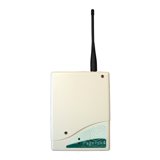
- Page 1 Pagetek MK4 10/5 Zone Paging Transmitter, DC Version Installation & User Manual PTMK4DCred Issue 2...
- Page 2 Scope has no control of the use and application of the frequencies issued by OFCOM. Some equipment that is licensed may have greater protection than other equipment which is operated on a WT Act License Exempt basis.
- Page 3 Hereby, the manufacturer Scope Communications UK Ltd declares that the radio equipment type: PageTek PT4512V, PT41012V, PT4524V, PT41024V, is in compliance with Radio Equipment Directive 2014/53/EU and ROHS Directive 2011/65/EU.
-
Page 4: System Overview
GPS unit or from various websites. One example is www.freemaptools.com/convert-postcode-to-ngr.htm Further information: Scope Sales team 01803 860700. OFCOM 020 7981 3131 or 0300 123 1000. Section 1: Installation The information contained in this Section is intended for authorised system installation engineers only. - Page 5 5 metres, always use low loss 50 ohm cable such as RG213 or UR67. Coaxial cable intended for TV, Satellite or CCTV installations is normally 75 OHM and therefore totally unsuitable for any transmitter installation manufactured by Scope. Also remember that the performance of the system will be affected by the type of material the unit is mounted on and its surroundings.
-
Page 6: Installation
If configured for voltage input (5-18V dc), the jumper link beside the relevant terminal must be positioned nearest the “V” symbol marked on the circuit board (see Diagram 2). If in doubt, check with Scope before proceeding; incorrect connection may cause permanent damage. - Page 7 Pagetek MK4 DC Power Version Installation WARNING! The circuit boards contain static sensitive components. Care should be taken to avoid contact wherever possible and anti-static precautions should be observed during installation. PTMK4DCred Issue 2...
- Page 8 Pagetek MK4 DC Power Version PTMK4DCred Issue 2...
-
Page 9: Section 2: System Operation
Pagetek MK4 DC Power Version Section 2: System Operation Confirmation of power connection is by way of the red PWR indicator on the front panel. Confirmation of transmit is by way of the momentary green TX indicator on the front panel. -
Page 10: Other Antennas
Pagetek MK4 DC Power Version Other Antennas The range and performance of this equipment can be improved by the addition of more efficient antennas*. These can be installed either inside or outside the building and are connected to the transmitter with 50 OHM coaxial cable. -
Page 11: System Specification
Relay output for Power Fail indication USB port for programming function only Footprint (mm): 184 (L) x 138 (W) x 45 (D) max excluding aerial Scope’s policy is one of continuous development and specifications are subject to change without prior notice PTMK4DCred Issue 2...
Need help?
Do you have a question about the Pagetek MK4 and is the answer not in the manual?
Questions and answers