Table of Contents
Advertisement
Quick Links
Instruction Manual
Form 1321
October 1997
Type 644 and 645 Differential Pressure Pump
Governors
Introduction
Scope of Manual
This instruction manual provides information on instal-
lation, adjustment, maintenance, and parts ordering for
the Type 644 and 645 differential pressure pump gov-
ernors. Refer to separate instruction manuals for in-
formation about the valve and other accessories used
with these actuators.
Only personnel qualified through training or experience
should install, operate, and maintain the Type 644 and
645 governors. If you have any questions about these
instructions, contact your Fisher Controls sales office
or sales representative before proceeding.
W2265-1 / IL
Figure 1. T ype 644 Actuator Mounted on
easy-e V alve Body
Types 644 and 645
Description
Type 644 and 645 actuators are used in combination
with any of several sliding stem valves to automatically
control steam-driven boiler feedwater pumps (recipro-
cating or turbine). The Type 644 or 645 actuator (see
figures 1 and 2), when used in combination with one of
several push-down-to-close sliding stem valves, forms
a pump governor.
Type 644 and 645 actuators may also be combined
with push-down-to-open valves to be used as relief
governors. Relief governors are used to divert excess
pump discharge back to the suction side of the pump.
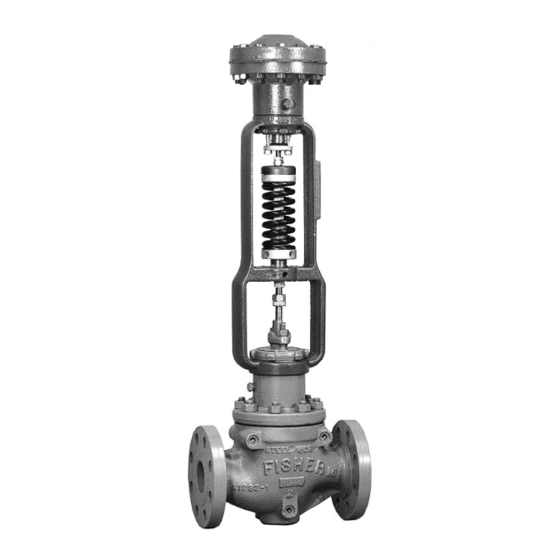
W2263-1 / IL
W2264-1 / IL
Figure 2 . T ypical Pump Governor Sectionals
Advertisement
Table of Contents

Related Manuals for Fisher 644


Summary of Contents for Fisher 644
- Page 1 This instruction manual provides information on instal- control steam-driven boiler feedwater pumps (recipro- cating or turbine). The Type 644 or 645 actuator (see lation, adjustment, maintenance, and parts ordering for figures 1 and 2), when used in combination with one of the Type 644 and 645 differential pressure pump gov- ernors.
-
Page 2: Installation
Direct Acting Actuators laws, rules and regulations. Proceed as follows to install Type 644 and 645 actua- If a leak develops in the system or if any tors that are used with push-down-to-close valves of the equipment is damaged, service is (Type 644-ED, Type 645-ED). -
Page 3: Reverse Acting Actuators
Type Type Number 500 psig 1000 psig Proceed as follows to install Type 644 and 645 actua- tors that are used with push-down-to-open valves Startup (Type 644-EDR, Type 645-EDR). Proceed as follows to startup direct acting actua- 1. Place the governor in the steam line. It may be tors (Type 644-ED, Type 645-ED). -
Page 4: Maintenance
The pump governor can be In figure 4, Type 644-EDR is being used as a relief isolated by throttling valve (D) and clos- governor maintaining a differential pressure between ing the shut-off valves (A, B, C and E). -
Page 5: Parts Ordering
(key 19) clockwise into the yoke. nameplate. Always mention this number when corre- 3. Disconnect the stem (key 22) and the diaphragm sponding with your Fisher Controls sales office or rod (key 14) by unscrewing the locknuts (key 31). sales representative regarding technical information or replacement parts. - Page 6 PARTS NOT SHOWN 28 DF9840-A / DOC SIZE 3 40A5422-B / DOC Figure 6. Type 645 Actuator Assembly Figure 5. Type 644 Actuator Assembly Description Part Number Description Part Number Stud Bolt, steel, Cd pl (2 req’d) Yoke Lock Nut, steel...
- Page 7 Size 1 (12 req’d) 1A685724052 Type 645 1A413224122 Size 2 (8 req’d) 1A444024052 Hex Nut, steel, Cd pl, Type 644 only Size 3 (12 req’d) 1A444024052 Boss Size 2-1/8 inch 1A680324122 Bolt Stud, steel, Type 645 Boss Size 2-13/16 inch 1A353724122 (8 req’d)
- Page 8 Types 644 and 645 Fisher, Fisher-Rosemount, and Managing The Process Better are marks owned by Fisher Controls International, Inc. or Fisher-Rosemount Systems, Inc. All other marks are the property of their respective owners. Fisher Controls International, Inc. 1976, 1997; All Rights Reserved...
Need help?
Do you have a question about the 644 and is the answer not in the manual?
Questions and answers