Table of Contents
Advertisement
Quick Links
Advertisement
Table of Contents

Related Manuals for Contec CNT24-4


Summary of Contents for Contec CNT24-4
- Page 1 CNT24-4(PCI) 24Bit Up/Down Counter Board for PCI User’s Guide...
-
Page 2: Trademarks
Copyright 1997 CONTEC Co., LTD. ALL RIGHTS RESERVED No part of this document may be copied or reproduced in any form by any means without prior written consent of CONTEC Co., LTD. CONTEC Co., LTD. makes no commitment to update or keep current the information contained in this document. -
Page 3: Product Configuration
Check the contents to make sure that you have everything listed above. If you do not have all the items, contact your distributor or CONTEC group office where you purchased. Note! Do not remove the board from its protective packaging until the computer case is open and ready for installation. -
Page 4: Table Of Contents
Procedure for use under Windows 95 version 4.00.950 or 4.00.950a ........15 Procedure for use under Windows 95 version 4.00.950B............15 Method of installing two or more CNT24-4(PCI) boards (for use under Windows 95 version 4.00.950 or 4.00.950a) ..............16 Method of installing two or more CNT24-4(PCI) boards (for use under Windows 95 version 4.00.950B) ..18... - Page 5 (Command CH0:01h, CH1:06h, CH2:0Bh, CH3:10h) ..................37 Counter Operation Mode ..........40 2-phase input...............40 Single-phase input ............40 Single-phase input with gate control ......41 Synchronization clear ..........42 Asynchronization clear ..........42 Count input multiplication .........43 Z-phase/CLR input (Command CH0:02h, CH1:07h, CH2:0Ch, CH3:11h) ..................44 CNT24-4(PCI)
- Page 6 QUESTIONS: ..............61 Is the pilot light on? ............61 Did the system boot up?..........61 Does your program work? ...........61 Does the sample program work? ........61 Is the input data accurate?.........62 Still have a problem? ..........62 7. Index ..............65 CNT24-4(PCI)
- Page 7 Connecting to Open-collector Output Device ..27 Figure 3.10. TTL-Level Input Circuitry ........28 Figure 3.11. Output Circuit and Connecting Example ....29 Figure 3.12. Photocoupler Input ..........30 Figure 3.13. TTL Input ...............30 Figure 3.14. Samples of Surge Voltage Protection.......31 Figure 4.1. Output port..............33 CNT24-4(PCI)
- Page 8 Figure 4.7. Example of Synchronization Clear ......42 Figure 4.8. Example of Asynchronization Clear......42 Figure 4.9. Counting Example for Multiplied Count Inputs..43 Figure 4.10. Number of Z-phase Inputs Available ZSE=0 (Positive Logic)............44 Figure 4.11. Digital Filter............47 Figure 5.1. Block Diagram............60 CNT24-4(PCI)
- Page 9 Table 4.5. Z-phase Input Mode...........44 Table 4.6. Digital Filter Clock Data..........47 Table 4.7. Relationship between programmable timer interrupt ................51 Table 4.8. Relationship Between One-shot Pulse Width Data and Pulse Width ............52 Table 4.9. Default Setting............57 Table 5.1. Specifications ............59 viii CNT24-4(PCI)
-
Page 10: Introduction
1. Introduction Thank you for purchasing the CNT24-4(PCI). The CNT24-4(PCI) is the PCI bus compatible. This board is plugged into a PCI bus expansion slot on the motherboard in the personal computer or into a PCI bus unit. You should read this... -
Page 11: Limited Three-Year Warranty
Please obtain a Return Merchandise Authorization Number (RMA) from the CONTEC group office where you purchased before returning any product. * No product will be accepted by CONTEC group without the RMA number. Liability The obligation of the warrantor is solely to repair or replace the product. -
Page 12: About The Manual
Introduction Chapter 2 Setup This chapter describes the procedures for setting up the CNT24-4(PCI) board and setting its switches. Chapter 3 Connecting the External Devices This chapter explains how to connect external devices to the board and gives notes on connecting them. - Page 13 Introduction CNT24-4(PCI)
-
Page 14: Setup
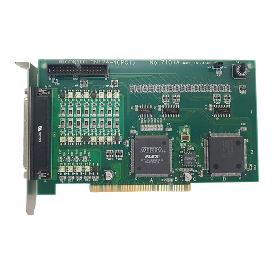
Setup 2. Setup Component Locations Figure 2.1. shows the names of major parts on the CNT24-4(PCI) board. Note that the switch setting shown below is the factory default. • Jumper for interrupt signal resource settings NOT USE • Interface connector... -
Page 15: Setting The Board Id
Setup Setting the Board ID If you install two or more CNT24-4(PCI) boards on one personal computer, set their respective board IDs to distinguish them. Assign a different value to each of the boards. The board IDs from 0 to F can be set to identify up to sixteen boards. -
Page 16: Setting The Interrupt Use
Setting the Interrupt Use If you don't use the Interrupt function, to save the Interrupt resources of PC, you can let recognize to the PC the CNT24-4(PCI) as no-Interrupt function boards. In case of interrupt use, this board is assigned the interrupt level from PC. -
Page 17: Setting Up The Board (For Use Under Ms-Dos Or Windows 3.1)
(1) Run the resource check program "CNTPCI.EXE" stored in the DOS directory on the supplied floppy disk (FD). (2) Check the I/O addresses and interrupt level (IRQ) displayed on the screen. Once the CNT24-4(PCI) has been set up correctly, it can be used under MS-DOS and Windows 3.1. CNT24-4(PCI) -
Page 18: Obtaining Resource Information
Setup Obtaining resource information You can get information on the personal computer resources assigned to the CNT24-4(PCI) by accessing the PCI BIOS. For the precise method, refer to the sample program stored in the DOS directory on the supplied FD. -
Page 19: Sample's Specification
*2 In the CNTPCI02, CNTPCI03, the digital filter is not set and the default is 100nsec. *3 To Output the signal to an external peripheral, CN1 must be connected. Note! Connect a signal appropriate for the input specification of an external peripheral. To connect a rotary encoder, see Chapter 3. "Connecting Rotary Encoder". CNT24-4(PCI) -
Page 20: Figure 2.5. Crt Display (Cntpci01.C)
• Set Z-phase • Set digital filter Read count value • Reset sense bit (Lower) (Middle) (Upper) Set count data (Lower) (Middle) Calculate count value (Upper) Display Set count match data count value (Lower) (Middle) (Upper) Figure 2.6. Flowchart (CNTPCI01.C) CNT24-4(PCI) -
Page 21: Figure 2.7. Crt Display (Cntpci02.C)
DATA 000000 000000 000000 000000 INTERRUPT COUNT 0TIME Figure 2.8. CRT Display (CNTPCI03.C) Note! To terminate the program, press the ESC key. If the program is terminated by another key, the interrupt routine is aborted and the process stops. CNT24-4(PCI) -
Page 22: Figure 2.9. Flowcharts (Cntpci03.C)
(Lower) Latch count value (Middle) Restore register (Upper) Read count value IRET Calculate count value Set count data (Lower) (Middle) Display (Upper) count value Interrupt process Reset sense bit Set IRQ5 Set IMR Stop timer Figure 2.9. Flowcharts (CNTPCI03.C) CNT24-4(PCI) -
Page 23: Setting Up The Board (For Use Under Windows 95)
OS used. This section describes the procedure and notes for using the board under Windows 95. Before the CNT24-4(PCI) can be used under Windows 95, have the OS recognize the I/O addresses and interrupt level (IRQ) to be used for the CNT24-4(PCI). -
Page 24: Procedure For Use Under Windows 95 Version 4.00.950 Or 4.00.950A
Distributed File From] field, then click on [OK]. (6) Follow the instructions on the screen to complete installation of the CNT24-4(PCI). After finishing installing the board, be sure to check the assigned resources. Procedure for use under Windows 95 version 4.00.950B (1) Set the board ID. -
Page 25: Method Of Installing Two Or More Cnt24-4(Pci) Boards (For Use Under Windows 95 Version 4.00.950 Or 4.00.950A)
Follow the procedure below to install two CNT24-4(PCI) boards for use under Windows 95 version 4.00.950 or 4.00.950a. (1) Check the board ID of the first CNT24-4(PCI) board, plug it into a PCI bus slot, then start up Windows 95 to install the first board correctly. - Page 26 Before trying to install the second board, check free resources on the personal computer. - The resources used for each CNT24-4(PCI) board do not depend on the location of the PCI bus slot or the board itself. If you...
-
Page 27: Method Of Installing Two Or More Cnt24-4(Pci) Boards (For Use Under Windows 95 Version 4.00.950B)
Follow the procedure below to install two CNT24-4(PCI) boards for use under Windows 95 version 4.00.950B. (1) Check the board ID of the first CNT24-4(PCI) board, plug it into a PCI bus slot, then start up Windows 95 to install the first board correctly. -
Page 28: Checking Resources
Before trying to install the second board, check free resources on the personal computer. - The resources used for each CNT24-4(PCI) board do not depend on the location of the PCI bus slot or the board itself. If you... -
Page 29: Support Software
Support software CONTEC provides the following driver software for Windows 95: API-CNT(98/PC)W95 Ver. 2.3 or later These pieces of driver software support up to four CNT24-4(PCI) boards. Note that, when API-CNT(98/PC)W95 is used, development languages that can be used are only 32-bit versions. Neither driver can be supported by any language dedicated to 16-bit applications. -
Page 30: Setting Up The Board (For Use Under Windows Nt)
OS used. This section describes the procedure and notes for using the board under Windows NT. Before the CNT24-4(PCI) can be used under Windows NT, have the OS recognize the I/O addresses and interrupt level (IRQ) to be used for the CNT24-4(PCI). -
Page 31: Checking Resources
(2) Select [Resources] (IRQ/port settings). Check the type and settings of resources assigned to the API-CNT(98/PC)NT and the conflicting device list. Once the CNT24-4(PCI) has been installed correctly, it can be used under Windows NT. Support software CONTEC provides the following driver software for Windows NT: API-CNT(98/PC)NT Ver. -
Page 32: External Connection
CN2 to an external device by connecting the optional cable to CN2. Matched pulse output is output from CN1. (Photocoupler insulated open collector output) Figure 3.1. Connecting the Interface Connector Note! See Chapter 3 "Option cable DT/B2" for further information. CNT24-4(PCI) -
Page 33: Connector
External Connection Connector Connecting the CNT24-4(PCI) board to external devices is via one 37-pin female D-Type connector (CN1) and one 30-pin male connector (CN2). • Installed connector 37-pin D-Type connector (female) • Suitable cable 17JE-23370-02(D8C) (male) (DDK) FDCD-37P (male) (HIROSE) -
Page 34: Figure 3.4. Cn2 Frontal View
OUT B/DOWN Ground Not Connected N.C. OUT A/UP General-purpose Input Ground OUT Z/CLR General-purpose Input OUT B/DOWN OUT Z/CLR OUT A/UP OUT B/DOWN Note! The VCC and GND signals are used for all four channels. Figure 3.5. CN2 Pin Assignments CNT24-4(PCI) -
Page 35: Optional Cable Dt/B2
OUT A/UP OUT A/UP OUT B/DOWN OUT B/DOWN OUT Z/CLR OUT Z/CLR General-purpose Input General-purpose Input Not connected N.C. Not connected N.C. N.C. Not connected Note! Each channel has an independent Plus Common. Figure 3.7. 37-Pin D-Type Connector Pin Assignments CNT24-4(PCI) -
Page 36: External Connection
External Connection You are now ready to connect the I/O cables to the board if you have not already done so. Connecting the CNT24-4(PCI) to external devices is via the 37-pin D-SUB I/O connector on the board. Figure 3.8. shows Digital input circuits. Figure 3.9. -
Page 37: Figure 3.10. Ttl-Level Input Circuitry
- The general input signal uses the same circuit structure. - The cable should be 1.5m or less. - To prevent malfunction caused by noise, separate the circuit as much as possible from other signal cables and noise sources. CNT24-4(PCI) -
Page 38: Output Circuit And Connecting Example
The board's output transistor does not have a surge voltage protection circuit. As a result, to run inductive loads (for example, relays and lamps), install surge voltage protection at the loading side. See "Appendix C: Surge Voltage" for further information. CNT24-4(PCI) -
Page 39: Connecting Rotary Encoder
(Connector pin number) Plus Common Power CH0 : 8 CH2 : 27 source CH1 : 18 CH3 : 37 CNT24-4(PCI) CH0 : 9 CH2 : 28 A-phase A-phase CH1 : 14 CH3 : 33 CH0 : 10 CH2 : 29... -
Page 40: Measures Against Voltages
Examples of measures against surge voltages are as shown in the Figure 3.14. below. Figure 3.14. Samples of Surge Voltage Protection Note! The protection circuit will not be effective unless it is installed less than 50cm from the load and contact. CNT24-4(PCI) - Page 41 External Connection CNT24-4(PCI)
-
Page 42: I/O Ports And Registers
In this case, the data is set from the lower bite, the middle byte and the upper byte. Data of 24 bits is read from the lower byte, the middle byte and the upper byte. Similarly, to set 32 bit data, output data four times to the +1 port. CNT24-4(PCI) -
Page 43: Count Value Flow
Set comparison Comparison CH0 : 01h register Register CH1 : 06h CH2 : 0Bh Command CH3 : 10h CH0 : 03h CH1 : 08h Output one-shot pulse CH2 : 0Dh (Command 19h) CH3 : 12h Figure 4.3. Count Value Flow CNT24-4(PCI) -
Page 44: Operation Command
CH3 LT CH2 LT CH1 LT CH0 LT Latch count value (4) No used TIME nterrupt latch (5) No used TIME Sense set (5) Programmable timer setting data Timer data (32) No used START Timer start (1) One-shot pulse width data One-shot pulse (8) CNT24-4(PCI) -
Page 45: Table 4.2. Input Command
CH2 read count value CH2 Read count value (24) CH2 Status data (8) CH3 read count value CH2 Read count value (24) CH2 Status data (8) TIME CH3 CH2 CH1 CH0 Interrupt mask (5) TIME CH3 CH2 CH1 CH0 Sense port (5) CNT24-4(PCI) -
Page 46: Output Command
SEL1 Execute an OUT command for output port +0, then set an operation mode on output port +1. RESET Clears the 24 bit up-down counter to "00000h." During RESET=0, counting is disabled. 0 : Clear counter 1 : Count CNT24-4(PCI) -
Page 47: Table 4.3. Counter Operation Mode
2-phase input, Asynchronization clear, Table4.4. Double multiplication mode 2-phase input, Asynchronization clear, Single multiplication mode Single-phase input, Asynchronization clear, Quadruple multiplication mode Single-phase input with gate control, Asynchronization clear, Double multiplication mode Single-phase input with gate control, Asynchronization clear, Double multiplication mode CNT24-4(PCI) -
Page 48: Table 4.4. Switching Counting Direction
I/O Ports and Registers Switches The rotary encoder counting direction. Table 4.4. Switching Counting Direction Rotary encoder rotation Clockwise Counterclockwise DOWN DOWN Note! In the default setting, all of channels are set 00h. CNT24-4(PCI) -
Page 49: Counter Operation Mode
Counting Figure 4.5. Single-phase Counting Example Note! This is a counting operation when DIR=1. If DIR=0, the counter counts down with the rising edge of an UP pulse and counts up with the rising edge of a DOWN pulse. CNT24-4(PCI) -
Page 50: Single-Phase Input With Gate Control
This is a counting operation when DIR=1. If DIR=0 and the gate control signal (B-phase/DOWN) is HIGH, the counter counts down with the rising edge of a single-phase pulse (A-phase/UP). If DIR=0 and the gate control signal is LOW, the counter stops. CNT24-4(PCI) -
Page 51: Synchronization Clear
Counting Figure 4.8. Example of Asynchronization Clear If DIR=0 and the B-phase is LOW, the counter starts counting down with the falling edge of the A-phase input. If ZSEL=0, the Z-phase input is available only when it is LOW. CNT24-4(PCI) -
Page 52: Count Input Multiplication
- Double-phase input - Single-phase input For single-phase input, only the single multiplication mode is available. (There is no double or quadruple multiplication.) - Single-phase input with gate control Figure 4.9. Counting Example for Multiplied Count Inputs CNT24-4(PCI) -
Page 53: Z-Phase/Clr Input (Command Ch0:02H, Ch1:07H, Ch2:0Ch, Ch3:11H)
Only the next Z-phase input is available. Every Z-phase input is available. * mark is the default setting. - Disabled Z-phase input - Only next Z-phase input is available - Every Z-phase input is available Figure 4.10. Number of Z-phase Inputs Available ZSE=0 (Positive Logic) CNT24-4(PCI) -
Page 54: Comparison Register (Command Ch0:03H, Ch1:08H, Ch2:0Dh, Ch3:12H)
OUT Address+0h, 03h (CH1 : Select comparison register) OUT Address+1h, E8h (Lower bits) OUT Address+1h, 03h (Middle bits) OUT Address+1h, 00h (Upper bits) In addition, a particular setting can output a one-shot pulse. (For more details, see "One-shot Pulse" description.) CNT24-4(PCI) -
Page 55: Digital Filter (Command Ch0:04H, Ch1:09H, Ch2:0Eh, Ch3:13H)
Since external input signals (except the general input signal) are read into the internal counter through the digital filter, these signals are read after a four clock delay of the sampling frequency. With the default setting, external input signal is read with 400nsec delay. CNT24-4(PCI) -
Page 56: Figure 4.11. Digital Filter
- Some noise causes more than a four clock delay of the set frequency. - If the level changes faster than the sampling clock frequency that has been set, the level change is invalid and there is no count. Latch count. CNT24-4(PCI) -
Page 57: Latch Count Value (Command 14H)
Setting these bits "0," enables the interrupt. Notes! - In the default setting, all of the four channels and the timer are disabled (1Fh). - However, to mask a channel or the timer will not effect the function of setting/resetting the related status. CNT24-4(PCI) -
Page 58: Sense Reset (Command 16H)
+1 clear the sense bit. The next interrupt signal can be generated. TIME : Resets the sense bit when the programmable timer count is up. CH3-CH0 : Resets the sense bit for count match of the channels. CNT24-4(PCI) -
Page 59: Programmable Time (Command Timer Data:17H, Timer Start:18H)
OUT Address+1h, FFh (Lowest bits) OUT Address+1h, 2Ch (Lower bits) OUT Address+1h, 31h (Upper bits) OUT Address+1h, 01h (Highest bits) OUT Address+0h, 18h (Select timer start) OUT Address+1h, 1h (Timer start) Note! In the default setting, the timer is disabled. CNT24-4(PCI) -
Page 60: Timer Interrupt Frequency
Programmable timer data (Hex) Timer interrupt High byte Low byte frequency 1msec 10msec 100msec 1sec 2sec 3sec 4sec 5sec 6sec 7sec 8sec 9sec 10sec 15sec 20sec 30sec 40sec 50sec 100sec 150sec 200sec * The accuracy is 0.01% of the setting frequency. CNT24-4(PCI) -
Page 61: One-Shot Pulse (Command 19H)
About 40.14msec About 49.97msec About 60.2msec About 70.04msec About 80.28msec About 90.11msec About 100.35msec About 104.45msec Notes! - The default is "Pulse width = 0 (00h)" (not output). - The pulse width may fluctuate depending on the connection load specification. CNT24-4(PCI) -
Page 62: Input Command
The default of the read-out register is not determined. The following sample program shows how to read the CH2 counter value : Address+0, 0Ah (Select CH2 count data) Address+1, (Lower bits) Address+1, (Middle bits) Address+1, (Upper bits) Note! First set the CH2 data latch to "1." CNT24-4(PCI) -
Page 63: Status Data
This status bit shows the counting direction of the current. 0 : Counting up 1 : Counting down EQ : Detected match 0 : Counter value and register value matched. 1 : Counter value and register value did not match. CNT24-4(PCI) - Page 64 - Since the status data of A-phase, B-phase and Z-phase is the data after the filtering process, it has a 4 clock delay in the frequency that has been set. - Z-phase logic is set by the ZSEL of the operation mode setting. CNT24-4(PCI)
-
Page 65: Interrupt Mask (Command 15H)
- If an interrupt is enabled and generated and the TIME bit or one of the CH3 to CH0 bits changes to "1" reset the corresponding sense bit to enable the next interrupt. For details on sense bit resetting, see "Sense Bit Reset" of the output port. CNT24-4(PCI) -
Page 66: Default Setting
24-bit up/down counter 000000h Digital filter 00h (0.1 µ sec) Status data 7Bh (not connected for external) Latch count value Interrupt mask 1Fh (all disable) Sense port Timer data 00000000h Timer start 00h (stop timer) One-shot pulse 00h (not output) CNT24-4(PCI) - Page 67 I/O Ports and Registers CNT24-4(PCI)
-
Page 68: System Reference
0 - 104.45msec (all channels) External Power 5 - 12VDC I/O Address 8 bits x 4 ports Dimensions 179.0 x 107.0 x 18.5 mm Power Consumption 5VDC, 400mA (Max.) Operation Temperature 0 - 50°C Relative Humidity 20 - 90% CNT24-4(PCI) -
Page 69: Block Diagram
System Reference Block Diagram The following is a block diagram of the CNT24-4(PCI) interface board. Sampling clock 16-bit counter for digital filter Photocoupler 24-bit read register resistance input (4channels) TTL level input 24-bit counter (4 channels) 24-bit comparator 24-bit compare register... -
Page 70: Troubleshooting
- Selected interrupt levels don't conflict with interrupts required by other devices or cards. - Try one of the sample programs provided on the disk and see if it works. Does the sample program work? Check the following: - Signals are connected to the correct pins. CNT24-4(PCI) -
Page 71: Is The Input Data Accurate
- Pin connections on the I/O cables are secure. - Signals are present at the external connectors. - Try using the CNT24-4(PCI) board with other non-essential boards removed. Remove other boards one by one, checking the CNT24-4(PCI) for successful operation after each board is removed. - Page 72 4. Name of the CONTEC board that you are using. 5. Names of other boards in the computer. 6. I/O addresses for the CONTEC board and all other boards. 7. Interrupt levels for the CONTEC board and all other boards.
- Page 73 Troubleshooting 10. Different I/O addresses you have tried. 11. Are you using your own program or a CONTEC sample program. 12. List AUTOEXEC.BAT. 13. List CONFIG.SYS. CNT24-4(PCI)
-
Page 74: Index
System Reference, 59 DT/B2, 23, 26 Trouble shooting, 61 Features, 1 Warranty, 2 I/O Port Assignment, 33 Windows 3.1, 8 I/O Ports, 33 Windows 95, 14 Interface Connector, 23 Windows NT, 21 Introduction, 1 MS-DOS, 8 Obtain Service, 2 CNT24-4(PCI) - Page 75 A-41-781 LZC6961 000707 [971007]...
- Page 76 : +81 (6) 6477-5219 Fax : +81 (6) 6477-1692 E-mail : intsales@osaka.contec.co.jp U.S.A. : CONTEC MICROELECTRONICS U.S.A. INC. 2161 O’ Toole Ave. Suite I, San Jose, CA95131, U.S.A. : +1 (408) 954-7700 Fax : +1 (408) 954-7710 E-mail : tech_support@contecusa.com EUROPE : CONTEC MICROELECTRONICS EUROPE B.V.
Need help?
Do you have a question about the CNT24-4 and is the answer not in the manual?
Questions and answers