
Subscribe to Our Youtube Channel
Related Manuals for Gaurdall Rascal Super

Summary of Contents for Gaurdall Rascal Super
- Page 1 This manual is from http://groups.msn.com/UKSecurityPanels www.thesecurityinstaller.co.uk Rascal Super Engineer Manual Contents 1. Introduction 2. System Planning 3. Mounting the Control Panel 4. Mounting Remote Keypads 5. Wiring Remote Keypads 6. Wiring Control Panel 7. Specification 8. Initial Power Up 9. Circuit Programming 10.
-
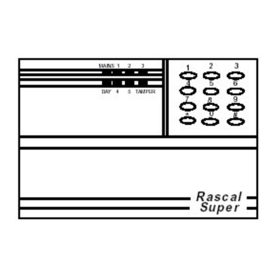
Page 2: Introduction
Please check defaults for suitability. The Rascal Super intruder alarm system consists of a main control panel and up to 3 remote keypads. The main control panel should be out of sight but remain accessible for programming or test. - Page 3 Mains should be supplied to the control panel via a fused spur. b) Battery Connection The Rascal Super requires a 1.9AH battery to be fitted to provide power in the event of a mains failure. c) Detector Circuits Connections are provided for up to five detector circuits.
- Page 4 Remote Keyswitch Two types of remote keyswitch can be connected to the Rascal Super system. One type in the remote keypad and one type as a separate option connected to the main PCB. j) Remote Keyswitch (in keypad) The Rascal Super control panel can be operated from a remote keyswitch.
-
Page 5: Specification
9. Circuit Programming The Rascal Super is designed to be fully programmable. The engineer should be familiar with all the programming options available to each circuit there are six circuit types with various options assigned to each. These are listed below. -
Page 6: Programming Examples
This manual is from http://groups.msn.com/UKSecurityPanels www.thesecurityinstaller.co.uk 10. Programming Examples To make circuit 1 an alarm circuit and isolate permit, proceed as follows: Press key 4 followed by key 1. Whilst in program mode clear all previous configurations. Press key 1 followed by key 6 (LED's 1 and tamper are on). Press * key to exit. To make circuit 2 an alarm circuit with walk through (entry route) and isolate permit, proceed as follows: Press key 4 followed by key 2. -
Page 7: Extended Programming
This manual is from http://groups.msn.com/UKSecurityPanels www.thesecurityinstaller.co.uk Part Set Exit Time If programmed for part set the part set exit time must be programmed as follows. From program mode press the '3'key followed by the '3' key. The time is programable from 5 - 105 seconds. -
Page 8: Engineer Logs
This manual is from http://groups.msn.com/UKSecurityPanels www.thesecurityinstaller.co.uk 13. Engineer Log Review The engineer log is organised into SET and UNSET events. The log will show the first to alarm and subsequent alarms as well as isolated circuits. First to alarm is shown by the relevant LED being 'ON'.
Need help?
Do you have a question about the Rascal Super and is the answer not in the manual?
Questions and answers