Advertisement
Quick Links
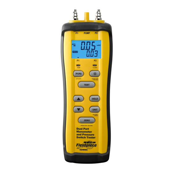
Fieldpiece
Dual Port
Manometer
and Pressure
Switch Tester
OPERATOR'S
MANUAL
Model
SDMN6
01
Specifications
Operating environment: 32°F to 118°F (0°C to 48°C) at <80% RH
Storage temperature: -4°F to 140°F (-20°C to 60°C), 0 to 80% RH
(with battery removed)
Power: 9V, NEDA 1604A, IEC 6LR61 9V alkaline battery.
Battery life (alkaline): 200 hours (manometer only, backlight off),
12 hours (pressure switch testing @ 27% pump speed, BL off,
approx -2.5"WC induced pressure w/o pump bleed accessory)
Auto power off (APO): 15 minutes
Low battery indication:
Units of Measure: inWC, mmWC, mbar, psi
Resolution: 0.01 inWC
Overrange: "OL" or "-OL" is displayed
Max Pressure: 900inWC (17.4psi) will damage sensors
Compatible media: Dry, non-corrosive gases
Pressure ports: 2 connectors (P1, P2)
for flexible tubing (4.5mm to 8mm ID)
Pump port: 1 connector (PUMP)
for 5mm (~3/16 inch) ID flexible tubing
Lead jacks: 2 banana plug jacks for testing open/close switch status
(continuity between terminals)
Accuracy: Stated accuracy at 0 to 50°C (32 to122°F): ±1.5% FS
Accuracy and ranges:
inWC: ±0.02 on 0.00 to ±2.00 (±1.5% FS on 2.00 to ±60.0);
mmWC: ±0.5 on 0.00 to ±51.0 (±1.5% FS on 51.0 to ±1500);
mbar: ±0.05 on 0.00 to ±5.00 (±1.5% FS on 5.00 to ±150.0);
psi: ±0.001 on 0.000 to ±0.07 (±1.5% FS on 0.07 to ±2.000)
06
Quick Start
1. Press
for 1 second to turn on your SDMN6.
2. If necessary, press ZERO for 1 second to set the
ambient pressure of P1 and P2.
3. P1 will be displayed in inches of water column
(inWC.) P1-P2 will be displayed on lower line.
4. See sections below for details on testing pres-
sure switches.
Scan for Video
Certifications
Get the free mobile app at
http:/ / gettag.mobi
C-Tick (N22675)
CE
WEEE
RoHS Compliant
02
Static Pressure
1. ZERO your SDMN6 while at ambient pressure
with any hoses/probes attached. This will zero
both P1 and P2. For measurements less than
2 inWC, take reading within 1 minute after
zeroing for best accuracy.
2. Use one hose (P1 or P2) to get the gauge pres-
sure relative to the ambient or ZERO pressure.
3. Connect both hoses if you want to see rela-
tive pressure, P1 - P2. This is common when
evaluating equipment such as a blower.
0.05
inWC
Blower
P1
PUMP
P2
-0.03
inWC
inWC
07
Description
Correct pressure switch operation is integral
to the safety of a furnace environment.
The SDMN6 is a dual-port manometer that
also accurately tests pressure switches by
simulating a draft with an internal pump.
Adjust the pump's speed to create a negative
pressure (vacuum). The red LED indicates when
the switch closes. View the closing/opening
pressures directly on the LCD.
The dual-port manometer measures ±60
inches of water column, high enough for gas
pressures.
Check building pressurization with static
pressure resolution of 0.01"WC. View P1-P2
in the bottom line of the display for checking
pressure differentials.
Use the static pressure probes to check for
a pressure drop accross two points in a duct.
This is useful for evaluating a blower or finding
airflow restrictions in the ductwork.
03
NOTE: Always use the static pressure probes if
checking static pressure of an airflow stream.
NOTE: The red arrows on the probes should
point toward the airflow stream.
>> AIRFLOW DIRECTION >>
4. You can press P1 / P2 to toggle the top display
between P1 and P2. Note: P1 - P2 is shown
in the bottom line of the LCD.
5. Press UNITS to select: inches of water column
(inWC), millimeters of water column (mmWC),
millibar (mBar), or pounds per square inch
(psi).
6. Your SDMN6 will turn off automatically after
15 minutes of inactivity if APO is shown.
To disable auto-power-off (APO) hold P1/P2
while turning on your SDMN6.
7. If you are in an environment where the tem-
perature is noticeably changing while you are
taking your reading, it is advised that you dis-
connect the meter from the hoses and ZERO
it relative to ambient before each reading.
08
Display
Auto Power Off
(APO) Enabled
Blinks When
Solid: Readings Held
Pump is ON
Blink: Auto-Capture Mode
Pump Speed Limit Reached
Leads Detect
Low Battery
Continuity
Controls
Hold for one second to toggle power.
Press to toggle backlight.
Hold for one second to zero
pressure of P1 and P2.
Select P1 or P2 on top display.
(Hold while powering ON to disable Auto-off.)
Select mbar, inWC, mmWC, or psi.
(Hold to check % battery remaining.)
04
Gas Pressure
P1
PUMP
P2
Gas
inWC
Manifold
Smaller end (3/16") of the adapter
Adapter
connects to SDMN6 tubing. Remove
(5/16" to 3/16")
the installed brass screw fitting
from tube so the adapter can be
inserted.
Adapter Tube
(5/16")
Outlet Pressure
Inlet Pressure
Tap Screw
Tap Screw
Inlet Pressure Tap
Outlet
Pressure Tap
09
Real Time Pressure
Measurement of P1 or P2
(mbar, inWC,mmWC, or psi)
P1/P2 Mode: P1-P2
Test Mode: Shows when
you are Increasing (InC) or
Decreasing (dEC) pump speed.
Indicates Whether P1 or P2
is Shown on Top Display Line
HOLD the displayed measurements.
In TEST mode: press to activate auto-capture mode.
The pressure reading will automatically HOLD
when the pressure switch closes or opens.
Enter pressure switch TEST mode and start the
pump (allow warm up to finish). Press again
to stop the pump and return to P1/P2 mode.
In TEST mode, increase pump speed (InC) to increase
the induced vacuum. (Holding increases faster.)
Decrease pump speed (dEC) to decrease the induced
vacuum. (Holding decreases faster.)
05
1. See manufacturer's specification for target
inlet and outlet pressures.
2. Shut off main gas supply to furnace.
3. Shut off power to furnace equipment.
4. Zero your SDMN6 while at ambient pressure
with hoses attached.
5. Remove outlet pressure tap screw, and insert
the brass screw fitting of the P1 hose into the
outlet pressure tap of the gas regulator.
NOTE: Some pressure taps have a 5/16" boss
instead of an insert screw. In this case, remove
the brass screw fitting from the P1 hose and
connect the included 5/16" adapter tube.
Loosen the tap screw about 1 revolution, and
slide the tube over the boss (see illustration
at left). Make sure the tube is over the boss
enough to prevent leakage.
6. Put furnace into operation (i.e. turn on gas
and power to the furnace, call for heating, and
have furnace ignite as if running it in normal
operation).
7. P1 will show the pressure coming out of the
regulator.
8. If you suspect high or low inlet pressure into
the regulator, connect P1 to inlet tap and P2
to outlet tap to see the pressure drop across
the regulator.
10
Advertisement

Related Manuals for Fieldpiece SDMN6


Summary of Contents for Fieldpiece SDMN6
- Page 1 Measurement of P1 or P2 Auto Power Off (mbar, inWC,mmWC, or psi) 1. Press for 1 second to turn on your SDMN6. to the safety of a furnace environment. (APO) Enabled The SDMN6 is a dual-port manometer that Blinks When...
-
Page 2: Limited Warranty
• CLOSED LED blinks rapidly. 2. Connect the 2 yellow hoses of the Y-splitter within the manufacturer's tolerance rating of • Dramatic fluctuations of pressure readings. to the P1 and PUMP ports of your SDMN6. the switch (typically ±10%). For Service Transducer Test...
Need help?
Do you have a question about the SDMN6 and is the answer not in the manual?
Questions and answers