Advertisement
Quick Links
Quick Start
1. Power on your STA2 by holding the
ON/OFF button for 1 second. There is
a 5 second count down as the meter
In- Duct Hot Wire
warms up.
2. Use the arrow buttons to cycle the
Anemometer
display between air velocity, volu-
metric flow (CFM) and temperature.
OPERATOR'S
3. Press the DUCT button to enter a
MANUAL
duct size.
4. Press and hold the HOLD (Average)
button to enter "Record Mode."
Model STA2
Record flow, velocity and tempera-
ture values, over time or at specific
points. Then average the recorded
80
values.
PRESS FOR
AUTO-OFF
1 SECOND
Certifications
ON/OFF
RECORD MODE
HOLD
AVERAGE
UNITS
DUCT
ENTER
CLEAR DATA
MAX/MIN
In-Duct
Hot Wire
Anemometer
STA2
01
02
Display Scrolling
Functions
1. At any point during operation the arrow keys
Backlight
may be used to change the display(s) on your
STA2 to show velocity, flow and temperature
1. Press the backlight button to toggle the backlight
measurements.
on/off at any time during the STA2's use.
Duct Setup
Note: The backlight will automatically shut off after 1
minute to conserve battery life.
1. Enables the STA2 to calculate volumetric flow
Hold
based on user entered information specific to the
equipment being worked on. Pressing the DUCT
1. The HOLD button toggles the Hold Function on/off.
button will lead you through the duct setup. (See
The Hold function will pause the measured values
the "Set up your STA2" section for detailed use of
on the upper and lower displays until cancelled.
this function.)
2. Pressing the HOLD button for longer than 2 seconds
Units Setup
will take the STA2 into "Record Mode." (Please see
the Record Mode section for more information.)
1. To enter the Units setup mode hold down the DUCT
Maximum/Minimum
button for 2 seconds.
2. Use the Arrow and ENTER buttons to select air
1. Pressing the MAX/MIN button activates the Max-
velocity, flow, temperature and length units.
Min function, holding the maximum and minimum
Note: Length units will also be used as area units for
values measured until cleared.
Free Area inputs during Duct setup.
2. Once the Max-Min function has been enabled,
3. Once all units are selected you will be returned to
pressing MAX/MIN cycles between displaying
the main display screen.
maximum (MAX), minimum (MIN) and real time
values (MAX MIN).
Clear Data
1. Press and hold the MAX/MIN button for 2 seconds
to CLEAR DATA, this erases all stored data points
and resets the Record Mode counter to zero.
07
08
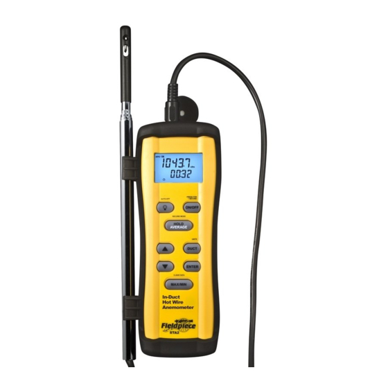
Description
Your STA2 is a portable, hand held,
hot wire anemometer, designed for
the HVAC/R technician.
The compact probe tip makes
directly measuring air velocity a
breeze. The 38"(96cm) telescoping
probe with laser etched ruling and
flattened edges allows you to locate
proper measurement points within a
duct and ensures that your probe is
properly aligned.
The STA2 calculates air flow
(CFM) based off your inputs of duct
dimensions or free area, making
for quick and accurate readings, no
matter the duct size or shape.
Use either of the averaging methods
in Record Mode to counter turbulent
C-Tick (N22675)
spikes in air velocity.
The dual display with a bright
CE
backlight, and rugged rubber boot
AUTO-OFF
with probe clips, make sure the STA2
AUTO-OFF
WEEE
is ready for any job.
AUTO-OFF
RoHS Compliant
AUTO-OFF
Fieldpiece STA2 In Duct Hotwire Anemometer
03
AUTO-OFF
AUTO-OFF
Record Mode
AUTO-OFF
AUTO-OFF
Record Mode allows you to find the Average,
AUTO-OFF
Maximum and Minimum of recorded
AUTO-OFF
measurements taken over a length of time, or in
different positions.
AUTO-OFF
1. Enter the Record Mode and select either time
or point recording. Time recording
continuous, a point recording
at entered points. Use the Arrow buttons to choose
between time and point recording and press ENTER
to lock in your selection.
2. a.)Time Recording: Use the ENTER button to start
and pause recording. The lower display shows the
AVERAGE
total time recorded.
b.) Point Recording: Press the ENTER button to
take a measurement at a specific point. The lower
display shows the total number of measurements
recorded.
3. Press the AVERAGE button to display the
average of recorded values. Press the MAX/MIN
button to display the maximum and minimum
measurements taken. These functions can be used
while still recording.
Note: Average replaces Hold while in Record Mode.
09
actoolsupply.com
actoolsupply.com
Display
Battery Life
Auto Power Off Enabled
AUTO-OFF
Volumetric Flow
Volumetric Flow
Volumetric Flow
RECORD MODE
Velocity (feet/minute)
HOLD
Velocity (meters/second)
AVERAGE
Velocity (kilometers/hour)
Velocity (miles/hour)
Temperature (Fahrenheit)
PRESS FOR
Temperature (Celsius)
1 SECOND
PRESS FOR
1 SECOND
AUTO-OFF
AUTO-OFF
Length (inches)
PRESS FOR
ON/OFF
1 SECOND
Length (centimeters)
PRESS FOR
ON/OFF
1 SECOND
Length (feet)
Length (meters)
ON/OFF
04
PRESS FOR
PRESS FOR
ON/OFF
1 SECOND
PRESS FOR
1 SECOND
CLEAR DATA
RECORD MODE
AUTO-OFF
1 SECOND
PRESS FOR
PRESS FOR
RECORD MODE
RECORD MODE
AUTO-OFF
PRESS FOR
1 SECOND
What is Free Area?
PRESS FOR
1 SECOND
MAX/MIN
ON/OFF
1 SECOND
HOLD
RECORD MODE
ON/OFF
1 SECOND
PRESS FOR
ON/OFF
HOLD
RECORD MODE
HOLD
How Do I Get It?
1 SECOND
AVERAGE
ON/OFF
RECORD MODE
AVERAGE
ON/OFF
AVERAGE
PRESS FOR
ON/OFF
HOLD
ON/OFF
Free Area is the total area through
1 SECOND
AVERAGE
ON/OFF
HOLD
which air can flow on either a supply
AVERAGE
RECORD MODE
will be
RECORD MODE
outlet or a return grille. Free area
AVERAGE
will only record
RECORD MODE
ON/OFF
is also sometimes referred to as
HOLD
RECORD MODE
HOLD
RECORD MODE
"effective area" or "see through area."
UNITS
RECORD MODE
HOLD
RECORD MODE
AVERAGE
UNITS
AVERAGE
RECORD MODE
If there is no grille or restriction on
HOLD
AVERAGE
HOLD
HOLD
the area through which air is flowing
PRESS FOR
HOLD
PRESS FOR
AVERAGE
DUCT
AUTO-OFF
1 SECOND
HOLD
UNITS
AVERAGE
then the free area is equal to the actual
RECORD MODE
AUTO-OFF
1 SECOND
DUCT
AVERAGE
UNITS
area. This would be the case if you
AVERAGE
HOLD
were measuring air flow in the middle
ON/OFF
DUCT
ON/OFF
of a duct, or if you were to remove the
AVERAGE
DUCT
UNITS
UNITS
grille from a supply or return.
UNITS
If you are measuring airflow where
UNITS
UNITS
DUCT
UNITS
there is a restriction present, then the
DUCT
UNITS
UNITS
ENTER
RECORD MODE
DUCT
RECORD MODE
free area is the total area minus the
ENTER
DUCT
area covered by the fins or grating.
DUCT
HOLD
DUCT
HOLD
DUCT
DUCT
UNITS
Free Area is published by grille
ENTER
AVERAGE
AVERAGE
manufacturers and is the most
CLEAR DATA
ENTER
accurate representation of the Free
CLEAR DATA
CLEAR DATA
DUCT
Area of a duct. Use manufacturer's
CLEAR DATA
MAX/MIN
ENTER
CLEAR DATA
data whenever available.
ENTER
ENTER
MAX/MIN
MAX/MIN
CLEAR DATA
UNITS
ENTER
MAX/MIN
ENTER
ENTER
ENTER
MAX/MIN
UNITS
ENTER
actoolsupply.com
CLEAR DATA
MAX/MIN
10
DUCT
CLEAR DATA
Point Recording
Time Recording
Average Display
Hold Display
PRESS FOR
AUTO-OFF
1 SECOND
Maximum Display
Minimum Display
AUTO-OFF
ON/OFF
PRESS FOR
AUTO-OFF
Free Area Input
1 SECOND
ON/OFF
AUTO-OFF
PRESS FOR
Duct Shapes
ON/OFF
AUTO-OFF
1 SECOND
AUTO-OFF
RECORD MODE
(cubic feet/minute)
ON/OFF
ON/OFF
80
Dimension Input
(liters/second)
ON/OFF
ON/OFF
HOLD
(diameter, height, width)
(cubic meters/hour)
RECORD MODE
PRESS FOR
PRESS FOR
RECORD MODE
AUTO-OFF
1 SECOND
AVERAGE
AUTO-OFF
1 SECOND
HOLD
HOLD
RECORD MODE
ON/OFF
RECORD MODE
RECORD MODE
ON/OFF
AVERAGE
AVERAGE
HOLD
HOLD
80
HOLD
80
AVERAGE
AVERAGE
AVERAGE
PRESS FOR
RECORD MODE
UNITS
AUTO-OFF
1 SECOND
RECORD MODE
80
UNITS
HOLD
UNITS
AVERAGE
HOLD
DUCT
PRESS FOR
DUCT
80
ON/OFF
1 SECOND
PRESS FOR
AVERAGE
DUCT
80
1 SECOND
ON/OFF
RECORD MODE
ON/OFF
ENTER
05
UNITS
DUCT
HOLD
ENTER
AVERAGE
ENTER
DUCT
How to Measure
ENTER
ENTER
80
CLEAR DATA
Accurate Airflow
CLEAR DATA
ENTER
ENTER
HOLD
CLEAR DATA
Find a Suitable Location
CLEAR DATA
MAX/MIN
MAX/MIN
CLEAR DATA
for a Traverse
CLEAR DATA
ENTER
MAX/MIN
DUCT
MAX/MIN
CLEAR DATA
MAX/MIN
1.
The cross sectional area at, before, and after the
MAX/MIN
traverse location should be either rectangular
CLEAR DATA
or round.
In-Duct
MAX/MIN
UNITS
In-Duct
2.
Make sure you have sufficient access around
UNITS
In-Duct
Hot Wire
the traverse location so that the duct may be
In-Duct
MAX/MIN
In-Duct
Hot Wire
In-Duct
traversed at multiple angles.
DUCT
Anemometer
Hot Wire
3.
The traverse location should be chosen so as to
Hot Wire
ENTER
Hot Wire
Hot Wire
DUCT
Anemometer
minimize the effects of leaks in the portion of
Anemometer
Anemometer
the system between the fan and the traverse
Anemometer
Anemometer
In-Duct
location.
In-Duct
CLEAR DATA
4.
The traverse location should be located far
enough downstream of the fan to allow the
Hot Wire
Hot Wire
airflow to come to a uniform distribution.
MAX/MIN
To determine an effective length, assume a
Anemometer
Anemometer
ENTER
minimum of 2.5 duct diameters for 2500ft/
ENTER
min or less and add 1 duct diameter for each
STA2
additional 1000ft/min measured. (For a
STA2
rectangular duct the equivalent diameter can
STA2
STA2
In-Duct
be calculated as D=√(4hw/π) where "h" is the
STA2
STA2
height of the duct and "w" is the width.)
Hot Wire
5.
Locations directly downstream from
obstructions, bends or sudden changes in the
Anemometer
duct are not good locations for a traverse.
STA2
11
Controls
PRESS FOR
AUTO-OFF
1 SECOND
Hold 1 second to toggle power on/off.
ON/OFF
PRESS FOR
PRESS FOR
AUTO-OFF
1 SECOND
AUTO-OFF
1 SECOND
PRESS FOR
AUTO-OFF
Toggle Backlight. (Hold while powering
1 SECOND
RECORD MODE
ON/OFF
ON/OFF
your STA2 on to disable APO.)
ON/OFF
HOLD
AVERAGE
PRESS FOR
Toggle display Hold (displays
RECORD MODE
RECORD MODE
1 SECOND
RECORD MODE
average of recorded values
HOLD
HOLD
HOLD
AVERAGE
AVERAGE
while in record mode).
UNITS
AVERAGE
Hold for 2 seconds or longer
PRESS FOR
AUTO-OFF
PRESS FOR
1 SECOND
DUCT
PRESS FOR
AUTO-OFF
1 SECOND
to enter/exit record mode.
PRESS FOR
PRESS FOR
1 SECOND
AUTO-OFF
1 SECOND
PRESS FOR
UNITS
ON/OFF
UNITS
1 SECOND
1 SECOND
ON/OFF
UNITS
ON/OFF
80
DUCT
DUCT
DUCT
Scroll up or down. Cycles displayed
80
RECORD MODE
ENTER
RECORD MODE
measurement parameters (CFM, Velocity,
80
RECORD MODE
HOLD
HOLD
AVERAGE
and Temp.)
80
HOLD
AVERAGE
CLEAR DATA
AVERAGE
ENTER
ENTER
80
ENTER
MAX/MIN
CLEAR DATA
CLEAR DATA
UNITS
UNITS
CLEAR DATA
Press for duct setup.
UNITS
MAX/MIN
MAX/MIN
DUCT
DUCT
Hold for 2 seconds for Units setup.
MAX/MIN
DUCT
80
80
80
80
Confirm Selection.
ENTER
ENTER
ENTER
CLEAR DATA
UNITS
CLEAR DATA
UNITS
Displays Maximum or Minimum
UNITS
CLEAR DATA
UNITS
MAX/MIN
MAX/MIN
values. Hold for 1 second to exit
MAX/MIN
DUCT
and clear stored values.
DUCT
DUCT
DUCT
UNITS
06
Set Up Your STA2
80
ENTER
Press the DUCT button to enter Duct setup mode and
choose to input either duct dimensions or Free Area.
1.
Duct dimensions: Use this option if measuring
UNITS
in a duct or at an obstruction-free Supply/Return.
2.
Use the arrow and ENTER buttons to select the
Duct dimensions icon.
3.
Use the arrow and ENTER buttons to select the
shape of the Duct.
4.
Use the arrow and ENTER buttons to enter either
the Height (H=) and Width (W=) of the duct
(for rectangular ducts) or the Diameter (D=) (for
round ducts).
1.
Free Area: Use this option if measuring at a
Supply/Return with an obstruction such as a
grille and the free area is known.
2.
Use the arrow and ENTER buttons to select the
Free Area icon.
3.
Use the arrow and ENTER buttons to enter the
manufacturer specified Free Area.
After the appropriate information is input you will be
returned to the main display screen.
When you are ready to execute the traverse you will
want to put the STA2 into RECORD mode and select
time recording. Use the ENTER button to start and stop
recording at each of the points along your traverse. How
long you record at each point depends on how much
variance you see while measuring.
Continued on reverse...
12
80
80
80
Advertisement

Related Manuals for Fieldpiece STA2


Summary of Contents for Fieldpiece STA2
- Page 1 RECORD MODE If there is no grille or restriction on Make sure you have sufficient access around HOLD the "Set up your STA2" section for detailed use of on the upper and lower displays until cancelled. AVERAGE HOLD (for rectangular ducts) or the Diameter (D=) (for 2.
- Page 2 0.926H measurements should be recorded. conduct multiple traverses at different locations. Insert the probe of the STA2 into the duct and use the flat edges of the probe to position the 0.712H probe tip so air flows directly past the sensor.
Need help?
Do you have a question about the STA2 and is the answer not in the manual?
Questions and answers