Advertisement
Table of Contents
- 1 Table of Contents
- 2 General Safety Precautions
- 3 EC Declaration of Conformity
- 4 Connection of Power Supply
- 5 Commands
- 6 Outputs and Accessories
- 7 Selection
- 8 Adjustments
- 9 Main Menu
- 10 Display Viewing Mode
- 11 Start-Up
- 12 Troubleshooting
- 13 Example Application of Automation with Two Swinging Door Wings
- Download this manual
IP1967EN
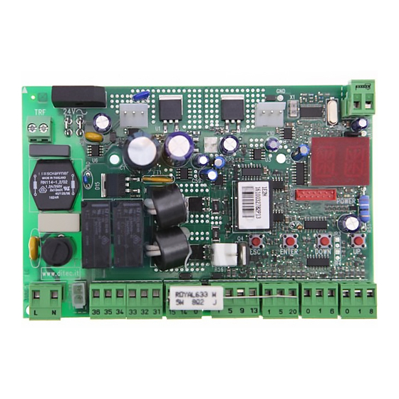
Ditec E2H
Installation manual for control panel for 2-motor 24V
automations with built-in radio
AUX
24V
ANT
JR5
TRF
Memory
card
BATK1
COM
GOL4
POWER
ESC
ENTER
DOWN
UP
F1
L N
36 35 34 33 32 31
15 14 0
1 5
9
13
1 5 20
0 1 6
0 1 8
JR1
BAT
24V=
24V=
Motor 2
Motor 1
L N
Power supply
www.entrematic.com
Advertisement
Table of Contents

Related Manuals for Entrematic Ditec E2H


Summary of Contents for Entrematic Ditec E2H
- Page 1 IP1967EN Ditec E2H Installation manual for control panel for 2-motor 24V automations with built-in radio Memory card BATK1 GOL4 POWER ENTER DOWN 36 35 34 33 32 31 15 14 0 1 5 20 0 1 6 0 1 8...
-
Page 2: Table Of Contents
All the rights concerning this material are the exclusive property of Entrematic Group AB. Although the con- tents of this publication have been drawn up with the greatest care, Entrematic Group AB cannot be held responsible in any way for any damage caused by mistakes or omissions in this publication. -
Page 3: General Safety Precautions
1. General safety precautions “Important instructions for installation safety. Incorrect installation can cause serious injury” This installation manual is intended for qualified personnel only. Installation, electrical connections and adjustments must be performed in accordance with Good Working Methods and in compliance with the present standards. Read the instructions carefully before installing the product. -
Page 4: Ec Declaration Of Conformity
2. EC declaration of conformity The manufacturer Entrematic Group AB, with headquarters in Lodjursgatan 10, SE-261 44 Land- skrona, Sweden, declares that the Ditec E2H type control panel complies with the conditions of the following EC directives: EMC Directive 2004/108/EC Low Voltage Directive 2006/95/EC R&TTE Directive 1999/5/EC. -
Page 5: Connection Of Power Supply
4. Connection of power supply Before connecting the power supply, make sure the plate data correspond to that of the mains power supply. An omnipolar disconnection switch with minimum contact gaps of 3 mm must be included in the mains supply. Check that upstream of the electrical installation there is an adequate residual current circuit breaker and a suitable overcurrent cutout. -
Page 6: Commands
5. Commands Command Function Description N.O. STEP BY STEP Selecting , the closure of the contact activates a closing or opening operation in the sequen- ce: open-stop-close-open. Warning: if automatic closing is enabled, the duration of the stop is selected via the selection OPENING Selecting , the closure of the contact... -
Page 7: Sofa1-Sofa2 Or Gopavrs Self-Controlled Safety Edge
SOFA1-SOFA2 or GOPAVRS self-controlled safety edge Command Function Description SAFETY TEST Insert the electronic card SOFA1-SOFA2 or GOPAVRS in the SOFA1-SOFA2 housing AUX on the control panel. GOPAVRS Selecting , the terminal 41 activates a safety edge test before each operation. If the test fails, an alarm mes- sage is visualised on the display. -
Page 8: Outputs And Accessories
6. Output and accessories Output Value - Accessories Description Power supply output for external accessories, including automa- tion status lamp. Electronically protected output. 24 V / 0,5 A Automation status lamp (proportional). The light switches off when the automation is closed; the light switches 24 V / 3 W on when the automation is open;... -
Page 9: Selection
7. Selection Description Display mode setting. Visualization mode. It is Maintenance mode. It is only possible to visualize possible to visualize and the values and parameters modify the values and pa- present. rameters present. The en- try in maintenance mode is indicated by the permanent switching on of the right- hand point. -
Page 10: Adjustments
9. Adjustment NOTE: before making all the automation adjustments, insert the dedicated memory module and press , or load the configuration applying to the automation installed (see options). When the power is connected or in the case of motor non-selection, the display will block all operations and give an error message. -
Page 11: Main Menu
9.3 Main menu use the keys to select the required function press the ENTER key to confirm Display Description AT - Automatic Configurations. The menu allows you to manage the automatic configurations of the control panel. BC - Basic Configurations. The menu allows to visualise and modify the main settings of the control panel. - Page 12 9.4 Second level menu - AT (Automatic Configurations) use the keys to select the required function press the ENTER key to confirm The procedures to activate the functions are described in the table. Display Description H0 - Predefined setting for residential use 0. This selection loads predefined values for certain standard parameters: AC - enabling of automatic closing : disabled...
- Page 13 9.5 Second level menu - BC (Basic Configurations) use the keys to select the required function press the ENTER key to confirm Display Description VS - Selecting mechanical stops verification. When enabled (ON), with every power supply connection the automation automatically checks the mechanical opening and closing end stops and/or the stop limit switches during opening and closing operation at the speed set with the adjustment...
- Page 14 Display Description SO - Enabling reversal safety contact functionality. When enabled (ON) with the automation idle, if the contact 1-8 is open, all operations are prevented. When disabled (OFF) with the automation idle, if the con- tact 1-8 is open, it is possible to activate the opening ope- ration.
- Page 15 9.6 Second level menu - BA (Basic Adjustments) use the keys to select the required function press the ENTER key to confirm WARNING: the gap between the adjustment values of the parameters may vary according to the type of automation. Display Description MT - Selection of automation type.
- Page 16 Display Description FA - Selection of opening limit switch mode. NO - None RA - Deceleration limit switch (after the activation, the door wing slows down its movement) NONE DECELERATION SX - Stop limit switch (after the activation, the door wing stops its move- ment) PX - Proximity limit switch STOP...
- Page 17 Display Description M2 - Setting motor 2 manoeuvre time. [s] Adjustment, in seconds, of the total manoeuvre time for motor 2. WARNING: adjustment occurs with a sensitivity in- terval of 0.5 sec, indicated by the switching on of the right-hand point. Example: = 7 seconds = 7,5 seconds...
- Page 18 Display Description LR - Setting electric lock release time. [s] ON - Active throughout the entire operation TS - Setting renewal of automatic closing time after safety release. [%] WO - Setting opening pre-flashing time. [s] Adjustment, in seconds, of the lead time for the switch-on of the flashing light, in relation to the start of the mano- euvre from a voluntary command.
- Page 19 9.7 Second level menu - RO (Radio Operations) use the keys to select the required function press the ENTER key to confirm The procedures to activate the functions are described in the table. Display Description SR - Transmitter memory storage..x2, x3...
- Page 20 Display Description C1 - Setting key 1 function of memorized transmitter. C2 - Setting key 2 function of memorized transmitter. C3 - Setting key 3 function of memorized transmitter. C4 - Setting key 4 function of memorized transmitter. NONE OPENING NO - None 1-3 - Opening command 1-4 - Closing command...
- Page 21 9.8 Second level menu - SF (Special Functions) use the keys to select the required function press the ENTER key to confirm The procedures to activate the functions are described in the table. Display Description SP - Setting the password (EXAMPLE) Note: this is only possible when the password is not set.
- Page 22 Display Description RC - Loading configuration. (EXAMPLE) It is possible to load the configurations previously saved, or load the predefined set- tings available in the memory positions . The predefined set- tings are as follows: : OBBI : FACIL : LUXO : ARC Loading a predefined setting, standard average values are automatically set for certain parameters (type of automation, operation speed, operation times and deceleration...
- Page 23 9.9 Second level menu - CC (Cycles Counter) use the keys to select the required function press the ENTER key to confirm The procedures to activate the functions are described in the table. Display Description CV - View total manoeuvres counter. = 241.625 manoeuvres (example) Note: view only.
- Page 24 9.10 Second level menu - AP (Advanced Parameters) use the keys to select the required function press the ENTER key to confirm WARNING: the gap between the adjustment values of the parameters may vary according to the type of automation. Given the complexity of the parameters, use of the Advanced Parameters menu is recom- mended only for qualified technical personnel.
- Page 25 Display Description TP - Setting of automatic closing time after partial ope- ning. [s] Adjustment occurs with intervals of varying sensitivity. - from 0 to 59 sec with 1 sec intervals; 0 SECONDS 59 SECONDS - from 1 to 2 min with 10 sec intervals. 1 MINUTE 2 MINUTES PO - Approaching/deceleration speed during opening.
- Page 26 Display Description SM - Selection of the operating mode of photocell terminals 1-6. (only with 00 - During manoeuvre, the opening of the safety contact stops movement with disengagement. 01 - During manoeuvre, the opening of the safety contact STOP + STOP + stops movement with disengagement.
-
Page 27: Display Viewing Mode
10. Display viewing mode WARNING: it is possible that, owing to the type of automation and control panel, certain menus are not available. 10.1 Automation status display WARNING: the automation status display mode is visible only with the Display viewing mode set on 02. - Page 28 1-5 - Step-by-step command. 1-6 - Safety with opening and closing stop. 1-8 - Safety with closing reversal. 1-9 - STOP command. P3 - Partial opening command. 3P - Hold-to-run opening command. 4P - Hold-to-run closing command. RX - Radio reception (of any memorised transmitter key present in the memory module). NX - Radio reception (of any key not memorised).
-
Page 29: Alarms And Anomalies Display
10.3 Alarms and anomalies display WARNING: alarms and anomalies are displayed when any display selection is made. The signaling of alarm messages takes priority over all other displays. Type of Display Description Remedy alarm M0 - Automation type not selected. If the dedicated memory module is present press Select a type of automation. - Page 30 Type of Display Description Remedy alarm A0 - Failure of test of safety sensor on Check the device SOFA1-A2 is working contact 6. correctly. If the supplementary SOF card is not in- serted, check the safety test is disabled. A3 - Failure of test of safety sensor on Check the device SOFA1-A2 is working contact 8.
-
Page 31: Start-Up
11. Starting WARNING: the system must have mechanical doorstops of appropriate strength or limit switches must be installed. WARNING: if this control panel is being used to replace a faulty one, it is possible to reset the last automation configuration by inserting the storage module of the old control panel in the housing on the new one, then loading the last configuration set with the command. -
Page 32: Troubleshooting
12. Troubleshooting Problem Possible cause Alarm Operation signalling The automation does not No power. Check power supply cable. open or close. Short circuited accessories. Disconnect accessories from terminals 0-1 (a voltage of 24V= must be present) and reconnect them one at a time. Contact Technical Service Blown line fuse. - Page 33 The remote control does not No storage module or incor- Switch the automation off and work rect storage module. plug in the correct storage module. Check the correct memorisa- tion of the transmitters on the built-in radio. If there is a fault with the radio receiver that is built into the control panel, the remote control codes can be...
-
Page 34: Example Application Of Automation With Two Swinging Door Wings
13. Example application of automation with two swinging door wings When the E2H control panel is used in applications for double 36 35 34 33 32 31 wings automations with over- lapping it is possible to make 24V= 24V= the following connections. Motor 2 Motor 1 (Fig. - Page 35 14. Example applications for automation with one swinging door wing When the E2H control panel is used in applications for single 33 32 31 wing automations it is possible to make the following connec- 24V= tions. Motor 1 (Fig. 14.1) Installation with mechanical door- stops in opening and closing phases, without the use of electric limit switches.
- Page 36 Entrematic Group AB Lodjursgatan 10 SE-261 44, Landskrona Sweden www.entrematic.com...
Need help?
Do you have a question about the Ditec E2H and is the answer not in the manual?
Questions and answers