Table of Contents
Advertisement
Quick Links
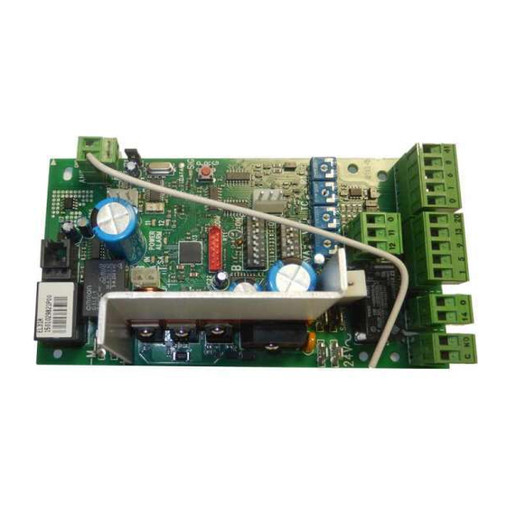
Ditec EL31R
Installation Manual for control panel for 24V automations with built-in radio.
BATK3
Safety switch
Transformer
Power supply
EL31R
Motor
-M
24V=
+M
B
A
IN
T
SA
B
ON
1
A
ON
1
24V~
SAFETY
C NO
14 0
F1
www.ditecentrematic.com
ENC
A
N
T
JR1
11
12
POWER
COM
SIG
PRG
2 3 4 5 6 7 8
2 3 4 5 6
VA
VC
TC
R1
12
11
0
1 5 9 13 20
0 1 6 8 41
IP1851EN
GOL4
Limit switch
Limit switch
Advertisement
Table of Contents

Related Manuals for Entrematic Ditec EL31R


Summary of Contents for Entrematic Ditec EL31R
- Page 1 Ditec EL31R IP1851EN Installation Manual for control panel for 24V automations with built-in radio. EL31R Motor 24V= BATK3 POWER 2 3 4 5 6 7 8 GOL4 2 3 4 5 6 Safety switch 24V~ SAFETY Transformer Limit switch Limit switch...
- Page 3 Index Subject Page General safety precautions EC declaration of conformity Technical specifications Applications Commands Self-controlled safety edge CROSS outputs and accessories QIK outputs and accessories Settings Trimmers CROSS dip-switches QIK dip-switches Jumper Signals Radio Working modes for sliding gates Start-up 10.1 CROSS start-up 10.2...
-
Page 4: General Safety Precautions
1. General safety precautions This installation manual is intended for qualified personnel only. Installation, electrical connections and adjustments must be performed in accordance with Good Working Methods and in compliance with the present standards. Read the instructions carefully before installing the product. Bad installation could be dangerous. The packaging materials (plastic, polystyrene, etc.) should not be discarded in the environment or left within reach of children, as these are a potential source of danger. -
Page 5: Ec Declaration Of Conformity
2. EC Declaration of Conformity The manufacturer Entrematic Group AB, with headquarters in Lodjursgatan 10, SE-261 44 Landskrona, Sweden, declares that the EL31R type control panel complies with the conditions of the following EC directives: EMC Directive 2004/108/EC Low Voltage Directive 2006/95/EC R&TTE Directive 1999/5/EC... - Page 6 4. Commands Command Function Description N.O. STEP-BY-STEP With DIP1A=OFF and TC<MAX, closing of the contact activates an opening or closing operation WITH AUTOMATIC in the following sequence: opening-stop-closing-opening. CLOSING N.B.: the stop is not permanent, but has the duration set with the TC trimmer. STEP-BY-STEP With DIP1A=OFF and TC=MAX, closing of the contact activates an opening or closing operation WITHOUT AUTOMATIC...
-
Page 7: Sliding Gates Outputs And Accessories
5. Sliding gates outputs and accessories Output Value - Accessories Description Accessories power supply. Power supply output for external accessories, including automation status lamps. 24 V 0.3 A The control panel is fitted with a housing for a plug-in card, such as radio receivers, magnetic SOFA1-SOFA2 loops, etc. - Page 8 6. Barrier outputs and accessories Output Value - Accessories Description Accessories power supply. Power supply output for external accessories, including automation status lamps. 24 V 0.3 A The control panel is fitted with a housing for a plug-in card, such as radio receivers, magnetic SOFA1-SOFA2 loops, etc.
- Page 9 7. Settings 7.1 Trimmers Trimmer Description VA - VC VA - Opening speed adjustment. Adjusts the opening speed. VC - Closing speed adjustment. Adjusts the closing speed. Setting automatic closing time. From 0 to 120 s. With DIP3A=OFF, once a safety switch has been activated, the counter starts as soon as the safety switch is re- leased (for example, after passing through the photocells), and lasts for a period of time set with TC (50%).
- Page 10 7.3 Barrier dip-switches DIP A Description DIP1A Command functions 1-5. Step-by-step Opening. N.B.: it also sets operating on the AUX plug-in card. DIP2A Selecting opening direction. Opening to the right. Opening to the left. The opening direction is intended by view- ing the automation from the side being examined.
- Page 11 7.5 Signals Flashing POWER Power supply on. Encoder not working or DIP5B selection is not con- ALARM sistent with the encoder actually being or not being there. Current overload on flashing light out- put. Shortcircuiting of flashing light driver. Command received or change in status of a dip-switch. At least one of the safety contacts is open or DIP6A selection is Safety test failure (terminal 41).
- Page 12 8. Radio 10 s The control panel is equipped with a radio receiver with a frequency of 433.92 MHz. The antenna consists of a rigid wire, 173 mm long, connected to the ANT clamp. It is possible to increase the range of the radio by connecting the antenna of the flashing lights, or by installing the tuned BIXAL antenna. N.B.: To connect the external antenna to the control panel, use a coaxial cable, type RG58 (max.
-
Page 13: Working Modes For Sliding Gates
9. Working modes for sliding gates The control panel can work in the following 3 modes: • automations with encoder (DIP5B=ON) and without stop limit switches, the automation stops on the mechanical stops; • automations with encoder (DIP5B=ON) and with stop limit switches, the automation stops after the stop limit switches have tripped; • automations without encoder (DIP5B=OFF) and with stop limit switches, the automation stops after the stop limit switches have tripped. In the automations with encoder (DIP5B=ON), by selecting DIP6B=ON, the control panel activates an innovative automatic detection system for the current necessary to move the automation at any point of the opening and closing operation. - Page 14 10.2. Starting the barriers WARNING The operations related to point 6 are performed without safeties. The trimmer can only be adjusted with the automation idle. The automation automatically slows when approaching the end stops or stop limit switches. After start-up the control panel receives a RESET and the first operation is performed at reduced speed (automation position acquisition).
-
Page 15: Troubleshooting
11. Troubleshooting Problem Possible causes Operation The automation does not open or close. No power. Check that the control panel is powered cor- (POWER ALARM LED off). rectly. Short circuited accessories. Disconnect all accessories from terminals 0-1 (POWER ALARM LED off). (a voltage of 24V= must be present) and recon- nect them one at a time. -
Page 16: Application Example For Sliding Gates
12. Application example for sliding gates When using the control panel for sliding automation applications: - Select the correct opening direction with DIP2A <MAX 2 3 4 5 6 7 DIP2B=ON DIP1A=ON (Example 1). When using the control panel for sliding gate 2 3 4 5 6 applications: - connect the opening and closing limit switch NC contacts... - Page 17 14. Example of parallel automations JR1=NO JR2=CH1 2 3 4 5 6 7 2 3 4 5 6 7 DIP1A=ON DIP1A=ON DIP2A=ON 2 3 4 5 6 2 3 4 5 6 1 5 9 13 20 0 1 6 8 41 1 5 9 13 20 0 1 6 8 41 It is possible to command two automations [A] and [B] in parallel with the connections and settings indicated in the figure.
- Page 18 15. Operator present function modes When the control panel is used in “operator present” <MAX function mode: 2 3 4 5 6 7 8 DIP2B=OFF - disconnect terminal 9; DIP1A=ON - set the opening direction with DIP2A=OFF; 2 3 4 5 6 In this state, the opening (1-5) and closing (1-6) controls function only if held in the pressed position, and the au- Closing limit switch...
- Page 19 All the rights concerning this material are the exclusive property of Entrematic Group AB. Although the contents of this publication have been drawn up with the greatest care, Entrematic Group AB cannot be held responsible in any way for any damage caused by mistakes or omissions in this publication.
- Page 20 Entrematic Italy S.p.A. Via Mons. Banfi, 3 • 21042 Caronno P.lla (VA) Italy Tel. +39 02 963911 - Fax +39 02 9650314 www.ditecentrematic.com...
Need help?
Do you have a question about the Ditec EL31R and is the answer not in the manual?
Questions and answers