Viessmann Vitoflame 100 Service Instructions Manual
Pressure-jet oil burner
Hide thumbs
Also See for Vitoflame 100:
- Service instructions manual (68 pages) ,
- Service instructions for contractors (56 pages) ,
- Service instructions manual (52 pages)
Table of Contents
Advertisement
Advertisement
Table of Contents

Related Manuals for Viessmann Vitoflame 100


Summary of Contents for Viessmann Vitoflame 100
- Page 1 VIESMANN Service instructions for contractors Vitoflame 100 Type VEH III Pressure-jet oil burner for Vitoplex 200 and 300, 80 to 300 kW for Vitorond 100 and 200, 80 to 270 kW for Vitoradial 300-T, 90 to 300 kW For applicability, see the last page VITOFLAME 100 Please keep safe.
-
Page 2: Safety Instructions
Safety instructions Safety instructions Please follow these safety instructions closely to prevent accidents and mate- rial losses. Safety instructions explained ■ all current safety regulations as defined by DIN, EN, DVGW, TRGI, Danger TRF, VDE and all locally applicable This symbol warns against the standards, risk of injury. - Page 3 ■ When using gas as fuel, also close the For replacements, use only orig- main gas shut-off valve and safeguard inal spare parts from Viessmann against unauthorised reopening. or those which are approved by ■ Isolate the system from the power sup- Viessmann.
-
Page 4: Table Of Contents
Index Index Commissioning, inspection, maintenance Steps – commissioning, inspection and maintenance.......... Further details regarding the individual steps............Burner control unit..................... 20 Troubleshooting Diagnosis......................24 Component overview..................29 Connection and wiring diagram................ 31 Parts list......................34 Commissioning/service report................41 Specification....................... 43 Standard values for burner settings.............. -
Page 5: Commissioning, Inspection, Maintenance
Commissioning, inspection, maintenance Steps – commissioning, inspection and maintenance For further information regarding the individual steps, see the page indicated Commissioning steps Inspection steps Maintenance steps Page • 1. Starting the heating system........... • • • 2. Checking the adjustment of the air damper servomotor.............. -
Page 6: Further Details Regarding The Individual Steps
Commissioning, inspection, maintenance Further details regarding the individual steps Starting the heating system To obtain optimum combustion values, the burner must be adjusted with the boiler at operating temperature (min. 60 ºC). Also carry out measurements at base load. Service instructions boiler circuit Note control unit For fuel details, see chapter "Information... -
Page 7: Checking The Adjustment Of The Air Damper Servomotor
Commissioning, inspection, maintenance Further details regarding the individual steps (cont.) Checking the adjustment of the air damper servomotor The switch cams have the following func- tions: Air damper closed (0º) Never alter the setting of Z. Ignition air setting ST1 Air damper setting stage 1 ST2 Air damper setting stage 2 Solenoid valve stage 2 The switch cams for ignition air stage 1... - Page 8 Commissioning, inspection, maintenance Further details regarding the individual steps (cont.) 01. Switch OFF the mains isolator and safeguard against unauthorised reconnection. 02. Unscrew plug "P" A from the oil pump. 03. Unscrew plug "V" B from the oil pump. Note This allows the oil to drain from the oil pump.
- Page 9 Commissioning, inspection, maintenance Further details regarding the individual steps (cont.) 07. If required, adjust the oil pressure at the pressure adjusting screw of the oil pump C (for Danfoss pumps, this may be either at the front or at the side of the pump, subject to pump type).
-
Page 10: Adjusting The Air Volume
Commissioning, inspection, maintenance Further details regarding the individual steps (cont.) Adjusting the air volume The air volume is preset at the factory. If required, adjust the air volume. For this, initially adjust the air volume for stage 2 on the blast tube connection. Starting up the burner may require some fine adjustment. -
Page 11: Checking The 0-Point Setting Of The Blast Tube Connection
Commissioning, inspection, maintenance Further details regarding the individual steps (cont.) Readjusting stage 1 1. Change service switch G to position II (automatic mode) and close the cover flap. 2. Adjust the burner at service switch G to stage 1. 3. Remove the cover from the servomo- tor. - Page 12 Commissioning, inspection, maintenance Further details regarding the individual steps (cont.) 1. Fit the burner cover on the burner casing. 2. Set the scale for blast tube connec- tion adjustment with blast tube con- nection adjusting screw A to "0". 3. Undo locking screw B. 4.
-
Page 13: Cleaning And Testing The Flame Monitor
Commissioning, inspection, maintenance Further details regarding the individual steps (cont.) Cleaning and testing the flame monitor Safety check Response Burner start with Fault shutdown at the covered flame end of the safety monitor time red flashing code, flashes 2x Burner start with Fault shutdown after flame monitor max. -
Page 14: Cleaning The Burner
Commissioning, inspection, maintenance Further details regarding the individual steps (cont.) Cleaning the burner For cleaning the combustion chamber and hot gas flues, see boiler service instructions. F Contactor (for 270 to 300 kW) 1. Set the burner in its maintenance 2. -
Page 15: Replacing The Nozzle
Commissioning, inspection, maintenance Further details regarding the individual steps (cont.) Replacing the nozzle 1. Remove nozzle cover with mixer device and position with blast tube connection above the burner housing (service position). This prevents the formation of bubbles in the blast tube connection. -
Page 16: Checking And Adjusting The Ignition Electrodes
Commissioning, inspection, maintenance Further details regarding the individual steps (cont.) Checking and adjusting the ignition electrodes Check ignition electrodes A for wear, contamination and size (see Fig.) and replace if required. +0.3 80 kW In conjunction with Vitorond 100, type VR2B 80 and 105 kW In conjunction with Vitoplex 300, type TX3 90 kW... - Page 17 Commissioning, inspection, maintenance Further details regarding the individual steps (cont.) + 0.3 130 to 225 kW In conjunction with Vitoplex 300, type TX3 140 and 235 kW In conjunction with Vitoplex 300, type TX3A, and Vitoradial 300- T, type VR3 150 and 200 kW In conjunction with Vitoplex 200, type SX2 160 to 230 kW...
-
Page 18: Cleaning Or, If Required, Replacing The Oil Pump Filter
Commissioning, inspection, maintenance Further details regarding the individual steps (cont.) Cleaning or, if required, replacing the oil pump filter Danfoss oil pump, type BFP 52 A Filter plug B O-ring (replace) C Filter (replace) -
Page 19: Operating And Service Documents
Commissioning, inspection, maintenance Further details regarding the individual steps (cont.) Suntec oil pump, type AT 2-55 A Filter (clean or replace) C O-rings (replace) B Flat gasket (replace) D Cover Operating and service documents 1. Complete and detach the customer registration card: ■... -
Page 20: Burner Control Unit
Burner control unit Burner control unit Program sequence during commissioning TR/STB Stage 2 BV2 control cam Stage 1 Start Required input signals Control signals Note The output signal at the solenoid valve stage 2 F is dependent upon the switch position of the control cam of the solenoid valve stage 2 in the servomotor. - Page 21 Burner control unit Burner control unit (cont.) Post-ignition time begins with flame max. 5 s (max. until end of "TSA") Start-up safety time max. 5 s Function and fault indications of the signal indicator (LED) In standard mode, operating conditions are displayed by colour codes through LED indicator A (see the following table).
- Page 22 Burner control unit Burner control unit (cont.) Burner fault sequence diagram System cold LED on burner control unit illuminates red Reset burner con- Call up flashing Call up data transfer trol unit: code: via interface (acces- Press reset button for Press reset button sories): approx.
- Page 23 Burner control unit Burner control unit (cont.) Burner start Burner start...
-
Page 24: Troubleshooting
Troubleshooting Diagnosis Faults with flashing code display Fault Cause Measures flashing code Burner does not 10 x Wiring fault or internal Check the electrical con- start (with fault indi- fault, other faults nection cation), indicator illuminates Burner does not 2 × Motor faulty Replace motor start (with fault dis-... - Page 25 Troubleshooting Diagnosis (cont.) Fault Cause Measures flashing code Pump does not sup- 2 × Shut-off valves closed at Open valves ply oil filter or in oil line 2 × Filter blocked Clean filter (pre-filter and pump filter), replace if required 2 ×...
- Page 26 Troubleshooting Diagnosis (cont.) Fault Cause Measures flashing code Burner starts and 2 × Flame monitor contami- Clean flame monitor flame builds, but nated burner cuts out after 2 × Flame monitor receives Clean sensor plate safety time expires insufficient light 2 ×...
- Page 27 Troubleshooting Diagnosis (cont.) Faults without flashing code display Fault Cause Measures Burner does not No voltage Check fuse or connector aBÖ start (no fault dis- in the control unit, the electrical play), indicator does connections, the setting of the not illuminate ON/OFF switch on the control unit and the mains isolator High limit safety cut-out acti-...
- Page 28 Troubleshooting Diagnosis (cont.) Fault Cause Measures content too Incorrect setting Check setting (see chapter "Standard values for burner settings") Infiltrating air Seal flue pipe at boiler flue out- let. Re-tighten the combustion chamber cover screws and those on the flue outlet cover. Excessive flue gas Excessive oil throughput Match oil throughput to rated...
-
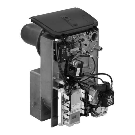
Page 29: Component Overview
Component overview Component overview A Service switch (for burner adjust- G Return line ment) H Suction line B Hood adaptor K Solenoid valve stage 2 C Quick-action fastener L Solenoid valve stage 1 D Electronic ignition M Contactor (for 270 to 300 kW) E Servomotor N Flame monitor F Burner control unit... - Page 30 Component overview Component overview (cont.) O Reset button X Blast tube connection P Oil line Y Flame tube R Oil pump Z Guide stays S Fan motor a Sensor plate T Fan housing b Oil burner nozzle U Impeller c Ignition electrodes V Inlet air silencer d Ignition cable W Air regulating valve...
-
Page 31: Connection And Wiring Diagram
Connection and wiring diagram Connection and wiring diagram 80 to 225 kW... - Page 32 Connection and wiring diagram Connection and wiring diagram (cont.) 270 to 300 kW...
- Page 33 Connection and wiring diagram Connection and wiring diagram (cont.) A Burner control unit (see chapter "Program sequence during commis- sioning") B Fault indicator C Reset button D Contactor E Burner motor F Burner stage 2 G Flame monitor H Electronic ignition K Fuel valve (BV1) L Fuel valve (BV2) M Servomotor for rotary damper...
-
Page 34: Parts List
Parts list Parts list When ordering spare parts: 039 Connecting cable, solenoid valve Quote the part no. and serial no. (see for oil pump stage 2 type plate) and the item no. of the 040 Connecting cable, solenoid valve required part (as per this parts list). for oil pump stage 1 Obtain standard parts from your local 041 Solenoid valve coil for oil pump... - Page 35 Parts list Parts list (cont.)
- Page 36 Parts list Parts list (cont.)
- Page 37 Parts list Parts list (cont.)
- Page 38 Parts list Parts list (cont.)
- Page 39 Parts list Parts list (cont.)
- Page 40 Parts list Parts list (cont.)
-
Page 41: Commissioning/Service Report
Commissioning/service report Commissioning/service report Setting and test values Commission- Maintenance/ (set values, see chapter "Standard values service for burner settings") Oil pressure ■ Stage 1 actual adjusted ■ Stage 2 actual adjusted Vacuum actual after mainte- nance Soot value ■ Stage 1 actual after maintenance ■... - Page 42 Commissioning/service report Commissioning/service report (cont.) Setting and test values Commission- Maintenance/ (set values, see chapter "Standard values service for burner settings") Flue gas loss ■ Stage 1 actual adjusted ■ Stage 2 actual adjusted Draught (at the back of the boiler) actual adjusted Blast tube con-...
-
Page 43: Specification
Specification Specification In conjunction with Vitoplex 200, type SX2 Rated boiler output 68/97 91/130 114/163 Burner output stage 1/2 Burner type VEH III-1SX VEH III-2SX VEH III-3SX DIN registration 5G1037/08S Voltage Frequency Power consumption Motor speed 2800 Version Two-stage Oil pump rate ⅜... - Page 44 Specification Specification (cont.) In conjunction with Vitoplex 300, type TX3 Rated boiler output 61/87 80/114 99/141 Burner output stage 1/2 Burner type VEH III-1TX VEH III-2TX VEH III-3TX DIN registration 5G1037/08S Voltage Frequency Power consumption Motor speed 2800 Version Two-stage Oil pump rate ⅜...
- Page 45 Specification Specification (cont.) In conjunction with Vitoplex 300, type TX3A, and Vitoradial 300-T, type VR3 Rated boiler output Burner output 69/98 86/125 106/152 stage 1/2 Burner type VEH III-1TX3A VEH III-2TX3A VEH III-3TX3A DIN registration 5G1037/08S Voltage Frequency Power consumption Motor speed 2800 Version...
- Page 46 Specification Specification (cont.) Rated boiler output ⅜ Connections R (female thread) Suction and return lines on the supplied oil hoses Max. permissible pre-charge pressure in the supply lines (with pipe circuits) In combination with Vitorond 100, type VR2B Rated boiler output 60/87 76/109 Burner output stage 1/2...
- Page 47 Specification Specification (cont.) Rated boiler output ⅜ Connections R (female thread) Suction and return lines on the supplied oil hoses Max. permissible pre- charge pressure in the supply lines (with pipe cir- cuits) In conjunction with Vitorond 200, type VD2 (cont.) Rated boiler output 175/250 205/293...
-
Page 48: Standard Values For Burner Settings
Standard values for burner settings Standard values for burner settings Note Check that the service instructions are applicable for the burner concerned (see notes on applicability, page 56, and the serial no. on the burner type plate). In conjunction with Vitoplex 200, type SX2 Rated output Oil burner nozzle Make: Danfoss... - Page 49 Standard values for burner settings Standard values for burner settings (cont.) Rated output Oil throughput Stage 1 kg/h 10.9 14.4 18.3 12.8 17.0 21.4 Stage 2 kg/h 11.9 15.6 20.6 26.1 11.3 14.0 18.3 24.3 30.7 Position of the switch cams of the air damper servomotor º...
- Page 50 Standard values for burner settings Standard values for burner settings (cont.) Rated output Blast tube connection setting Air inlet aperture set- ting In combination with Vitorond 100, type VR2B Rated output Oil burner nozzle Make: Fluidics Type 60°SF 60°SF Oil pressure approx. Stage 1 bar min.
- Page 51 Standard values for burner settings Standard values for burner settings (cont.) Rated output 12.1 14.5 17.3 20.3 Stage 2 kg/h 11.4 14.6 17.8 21.0 24.7 13.5 17.3 21.0 24.8 29.0 Position of the switch cams of the air damper servomotor °...
-
Page 52: Appendix
The use of fuel oil additives that leave residues is not permitted. Combustion improvers Combustion improvers are additives for optimising fuel oil combustion. Viessmann oil burners do not require combustion improvers, as these burners operate with clean and efficient combus- tion. -
Page 53: Keyword Index
Keyword index Keyword index 0 point of blast tube connection, check- Diagnosis ing............11 ■ Faults with flashing code display..24 ■ Faults without flashing code display27 Additives for fuel oil......52 Air damper position......7 Flame monitor, safety check....13 Air volume adjustment.......10 Flame monitor cleaning and testing...13 Flashing code ........24 Fuel oil Biofuels..........52... - Page 56 7441309 7441310 7441311 7441312 7441313 7441314 7441315 7441316 7441317 Viessmann Werke GmbH&Co KG Viessmann Limited D-35107 Allendorf Hortonwood 30, Telford Telephone: +49 6452 70-0 Shropshire, TF1 7YP, GB Fax: +49 6452 70-2780 Telephone: +44 1952 675000 www.viessmann.com Fax: +44 1952 675040...
Need help?
Do you have a question about the Vitoflame 100 and is the answer not in the manual?
Questions and answers