Viessmann Vitoflame 100 Service Instructions Manual
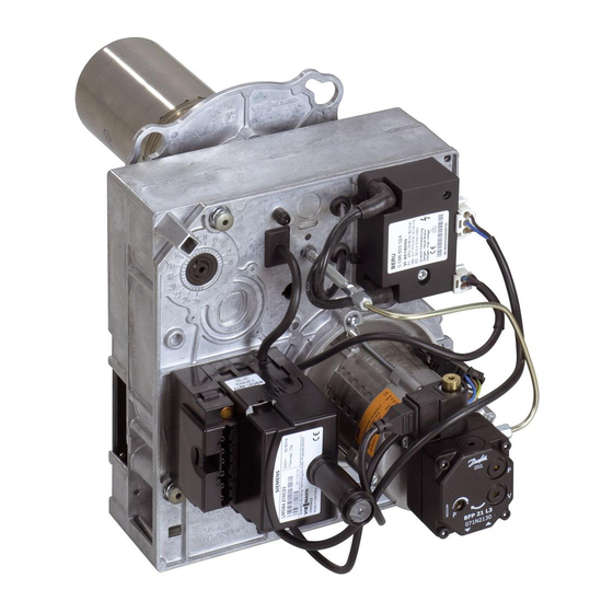
Pressure jet gas burner for vitoplex 100 rated output 90 to 210 kw
Hide thumbs
Also See for Vitoflame 100:
- Service instructions manual (56 pages) ,
- Service instructions for contractors (56 pages) ,
- Service instructions manual (52 pages)

Related Manuals for Viessmann Vitoflame 100


Summary of Contents for Viessmann Vitoflame 100
- Page 1 Vitoflame 100 See notes on applicability, page 2. VITOFLAME 100 Vitoflame 100 gas burner fitted to Vitoplex 100 Please keep safe...
-
Page 2: Safety Instructions
Safety instructions Please follow these safety instructions closely to prevent accidents and material losses. Work on the equipment Repair work Initial start-up Instructing the system user Work on gas equipment ¨ Safety instruction In this instruction manual, this heading denotes information which must be observed to prevent accidents and material losses ¨... - Page 3 Index General information Initial start-up, inspection and maintenance Troubleshooting Component summary Connection and wiring diagrams Parts list Appendix Operating and service documents...
-
Page 4: Steps Initial Start-Up, Inspection And Maintenance
Steps initial start-up, inspection and maintenance For further instructions on individual steps, see pages indicated. 1. Commissioning preparations 2. System start-up 3. Checking adjustment of the air damper actuator 4. Checking static and supply pressure 5. Checking nozzle pressure 6. Adjusting start-up gas volume 7. - Page 5 Steps initial start-up, inspection and maintenance For further instructions on individual steps, see pages indicated. 21. Checking all gas unions for leaks 22. Implementing final tests...
-
Page 6: Commissioning Preparations
Further details regarding the individual steps Commissioning preparations Leak test ¨ Safety instruction Check the test nipple for gas leaks. Please note: Vent the gas supply pipe and the gas float before initial start-up. To do this, route the vent pipe outdoors. - Page 7 Further details regarding the individual steps Function test without gas supply...
-
Page 8: Further Details Regarding The Individual Steps
Further details regarding the individual steps To obtain the optimum combustion values, it is essential to adjust the burner with the boiler heated to operating temperature (min. 60 ºC). Also carry out measurements at base load. System start-up Service instructions Boiler control unit. - Page 9 Further details regarding the individual steps Checking adjustment of air damper actuator º Never alter the ST 0 setting. Rated output range Boiler output Standard values for switching cams º º º...
- Page 10 Further details regarding the individual steps Checking static and supply pressure Check the type of gas with your local gas supplier. The burner is factory-set to natural gas E. Adjust the nozzle pressure for operation with natural gas LL according to the table on page 47.
- Page 11 Further details regarding the individual steps Supply pressure Please note: Initial start-up, see page 8. Switch the burner to stage 2. To do this, activate the emissions test switch on the control unit. Please note: The supply pressure (flow pressure) should be between 20 and 25 mbar.
- Page 12 Further details regarding the individual steps Checking nozzle pressure Please note: During the adjustment, also check the gas throughput by means of a volumetric test.
- Page 13 Further details regarding the individual steps Please note: Never turn the pressure regulator outside its setting range. Turn set screw F only as long as the nozzle pressure noticeably changes. Main volume butterfly D should be turned fully to "+". Adjusting stage 2 Please note: Start the burner in stage 2.
- Page 14 Further details regarding the individual steps Adjusting start-up gas volume The opening characteristics of the gas solenoid valve have been matched to the boiler and been preset at the factory. Generally you do not need to change this setting. Please note: At the factory, the quick-action is fully set to "+".
-
Page 15: Air Volume Adjustment
Further details regarding the individual steps Air volume adjustment The air volume is preset at the factory. If necessary, readjust the air volume, first adjusting the air volume for stage 2. Fine adjustment stage 2 ³ ³ ³ ³... - Page 16 Further details regarding the individual steps Fine adjustment stage 1 lÖ ³ ³ Please note: Adjust switching cams ST 1 (fine adjustment) in small steps. The set value for switching cam MV must not lie below the set value of switching cam ST 1 and not above that of switching cam ST 2.
- Page 17 Further details regarding the individual steps Checking ionisation current Please note: When checking with a Testomatik Gas, test cable no. 1 is required. You can also carry out this check with a multimeter. Please note: The system then initiates a fault shutdown.
-
Page 18: System Shutdown
Further details regarding the individual steps Checking air pressure switch At the factory, the air pressure switch is adjusted to the corresponding switching point, so that readjustment is generally not required. However, should an adjustment nevertheless be required, check the air pressure switch setting and correct, if required, in accordance with the details below by rotating black scaled ring B. - Page 19 Further details regarding the individual steps Cleaning burner For cleaning the combustion chamber and hot gas flues, see boiler service instructions.
- Page 20 Further details regarding the individual steps Cleaning gas orifices in sensor plate (if necessary) Please note: Observe the correct orientation of the gas orifices in the end plate (see page 21).
- Page 21 Further details regarding the individual steps Checking ignition and ionisation electrodes 90 to 100 kW 125 to 210 kW...
- Page 22 Further details regarding the individual steps Checking both valves of the gas train for leaks Please note: Only a function test is required for gas trains with leak test device. ³ ¨ Safety instruction Check the test nipple for gas leaks.
- Page 23 Further details regarding the individual steps Checking filter insert of gas train (make: Dungs)
- Page 24 Further details regarding the individual steps Checking all gas unions for leaks Implementing final tests Please note: The flue pipe must be sealed at the boiler adaptor. Infiltrating air leads to false measurements.
- Page 25 Diagnostics Safety time: max. 2 s Interval time stage I II: approx. 8 s Interval until the program shuts down approx. 23 s Running time for the actuator Function sequence approx. 2 s Interval until the flame is formed Start command Burner operating position Delay: approx.
- Page 26 Diagnostics Burner control unit...
- Page 27 Diagnostics Diagnosis of fault causes Fault code table Fault Possible cause...
- Page 28 Diagnostics Fault/behaviour Flashing Cause Remedy of the system code red...
- Page 29 Diagnostics Fault/behaviour Flashing Cause Remedy of the system code red...
- Page 30 Diagnostics Fault/behaviour Flashing Cause Remedy of the system code red µ...
- Page 31 Diagnostics Fault/behaviour Flashing Cause Remedy of the system code red µ...
- Page 32 Diagnostics Fault/behaviour Flashing Cause Remedy of the system code red...
- Page 34 Component summary...
-
Page 35: Component Summary
Component summary... -
Page 37: Connection And Wiring Diagram
Colour coding to DIN/IEC 757 Connection of assembly modules and accessories via system plug-in connector (e.g. Vitoair, gas valve leak detector kit, extension lead, etc.) Please note: The wiring diagrams on the following pages only apply in conjunction with Viessmann products. - Page 38 Connection and wiring diagram...
- Page 39 Connection and wiring diagram...
-
Page 40: Parts List
Parts list When ordering spare parts Parts Only for serial no. 7174933 3 00001 kkk and 7174934 3 00001 kkk. aCÖ... - Page 41 Parts list...
- Page 42 Parts list...
- Page 43 Parts list...
- Page 44 Parts list...
- Page 45 Parts list...
-
Page 46: Specification
Specification Rated output range Boiler output Burner output 1 /2 stage Type of burner Product ID Voltage Frequency Power consumption Motor speed Version Gas supply pressure Gas connection Corresponds to the boiler rated thermal load. -
Page 47: Standard Values For Burner Settings
Standard values for burner settings Please note: Check that the service instructions are valid for the burner concerned (see notes on applicability, page 2 and serial no. on the burner type plate). Nozzle pressure table Rated boiler output in kW Rated boiler output in kW 100 125 140 150... - Page 48 Standard values for burner settings Mixer setting Rated output range Boiler output Standard values for mixer setting Gas throughput subject to the operational net calorific value (H Rated boiler output Rated boiler output 90 to 100 kW 125 to 140 kW Boiler output 90 kW 100 kW...
- Page 49 Standard values for burner settings Gas throughput subject to the operational net calorific value (H Rated boiler output Rated boiler output 150 to 165 kW 190 to 210 kW Boiler output 150 kW 165 kW 190 kW 210 kW Please note: Partial load gas throughput equals 60 % of full load gas throughput.
-
Page 50: Commissioning/Service Report
Commissioning/service report Setting and test values Set value Initial start-up Date: Static pressure mbar Supply pressure (flow pressure) mbar mbar tick gas type Nozzle pressure mbar mbar mbar mbar Ionisation current µ µ Carbon dioxide % by vol. content CO % by vol. - Page 51 Maint./service Maint./service Maint./service Maint./service...
- Page 52 Commissioning/service report Setting and test values Set value Initial start-up Date: % by vol. Oxygen content % by vol. % by vol. % by vol. Carbon monoxide content CO content CO º C Gross flue gas temperature º C º C º...
- Page 53 Maint./service Maint./service Maint./service Maint./service...
- Page 54 Commissioning/service report Setting and test values Set value Initial start-up Date: Output Switch cam º position at the air º damper actuator damper actuator º º º º Static burner mbar pressure mbar mbar mbar Mixer assembly ring no. ring no.
- Page 55 Maint./service Maint./service Maint./service Maint./service...
- Page 56 Commissioning/service report Setting and test values Set value Maint./service Date: Static pressure mbar Supply pressure (flow pressure) mbar mbar tick gas type Nozzle pressure mbar mbar mbar mbar Ionisation current µ µ Carbon dioxide % by vol. content CO % by vol. % by vol.
- Page 57 Maint./service Maint./service Maint./service Maint./service...
- Page 58 Commissioning/service report Setting and test values Set value Maint./service Date: % by vol. Oxygen content % by vol. % by vol. % by vol. Carbon monoxide content CO content CO º C Gross flue gas temperature º C º C º...
- Page 59 Maint./service Maint./service Maint./service Maint./service...
- Page 60 Commissioning/service report Setting and test values Set value Maint./service Date: Output Switch cam º position at the air º damper actuator damper actuator º º º º Static burner mbar pressure mbar mbar mbar Mixer assembly ring no. ring no.
- Page 61 Maint./service Maint./service Maint./service Maint./service...
- Page 62 Commissioning/service report Setting and test values Set value Maint./service Date: Static pressure mbar Supply pressure (flow pressure) mbar mbar tick gas type Nozzle pressure mbar mbar mbar mbar Ionisation current µ µ Carbon dioxide % by vol. content CO % by vol. % by vol.
- Page 63 Maint./service Maint./service Maint./service Maint./service...
- Page 64 Commissioning/service report Setting and test values Set value Maint./service Date: % by vol. Oxygen content % by vol. % by vol. % by vol. Carbon monoxide content CO content CO º C Gross flue gas temperature º C º C º...
- Page 65 Maint./service Maint./service Maint./service Maint./service...
- Page 66 Commissioning/service report Setting and test values Set value Maint./service Date: Output Switch cam º position at the air º damper actuator damper actuator º º º º Static burner mbar pressure mbar mbar mbar Mixer assembly ring no. ring no.
- Page 67 Maint./service Maint./service Maint./service Maint./service...
-
Page 68: Keyword Index
Keyword index...
Need help?
Do you have a question about the Vitoflame 100 and is the answer not in the manual?
Questions and answers