Table of Contents
Advertisement
Quick Links
READ AND SAVE THESE INSTRUCTIONS
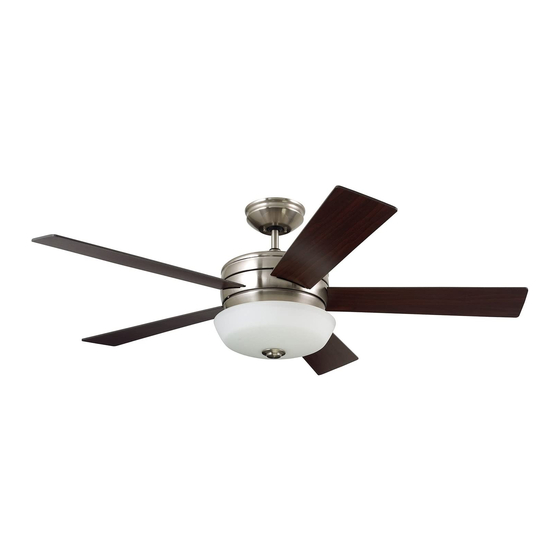
54" Ceiling Fan Owner's Manual
CF411BS00 -
CF411ORB00 -
Questions, problems, missing parts: Before returning to the store call Emerson Electric Customer Service
Part No. F40BP75200000
Revision: 170216
CRONLEY
Model Numbers
Brushed Steel
Oil Rubbed Bronze
23.6
Net Weight:
8 a.m. - 6 p.m., Eastern, Monday-Friday
1-800-654-3545
™
Lbs.
• Español - página 29
• Français - page 57
Form No. BP7520
U.L. Model No.: CF411
Advertisement
Table of Contents

Related Manuals for Emerson Cronley CF411BS00


Summary of Contents for Emerson Cronley CF411BS00
- Page 1 CF411ORB00 - Oil Rubbed Bronze 23.6 Net Weight: Lbs. Questions, problems, missing parts: Before returning to the store call Emerson Electric Customer Service 8 a.m. - 6 p.m., Eastern, Monday-Friday • Español - página 29 1-800-654-3545 • Français - page 57 Part No.
-
Page 2: Table Of Contents
4. Do not operate reversing switch until fan blades have UC7067RAL, manufactured by Rhine Electric Co., Ltd. come to a complete stop. To avoid fire, shock or injury, do not use an Emerson or any other brand of control not specifically approved for Additional Safety Instructions for Installation this fan. -
Page 3: Unpacking Instructions
Emerson Electric Co. Substitution of parts or accessories not designated Coupler Cover for use with this product by Emerson Electric Co. could Fan Blades result in personal injury or property damage. Blade Support Plates... -
Page 4: Electrical Requirements
This Manual Is Designed to Make it as Easy as Possible for You to Assemble, Install, Operate and Maintain Your Ceiling Fan Tools Needed for Assembly Your Emerson ceiling fan comes supplied with a Fan/Light Remote Control which consists of a receiver mounted One Phillips Head Screwdriver One Stepladder inside the ceiling cover of the fan motor housing. -
Page 5: Ceiling Fan Assembly
3. Ceiling Fan Assembly Remove the Hanger Ball by loosening the Phillips Head GREEN GROUND WIRE Set Screw in the Hanger Ball until the Ball falls freely down the Downrod (Figure 1). Remove the Pin from the Downrod, then remove the Hanger Ball (Figure 1). - Page 6 3. Ceiling Fan Assembly (Continued) Align the Clevis Pin holes in the Downrod with the holes in the Motor Coupler. HAIRPIN Install the Clevis Pin and secure with the Hairpin Clip CLIP CLEVIS (Figure 4). The Clevis Pin must go through the holes in the Motor HAIRPIN Coupler.
- Page 7 3. Ceiling Fan Assembly (Continued) The fan comes with Black, Blue and White Wires that are 1/2-INCH BLUE WIRE 80” long. BLACK WIRE Measure up approximately 6 to 9-inches above top of Hanger Ball / Downrod Assembly (Figure 7). WHITE WIRE 6 TO 9 INCHES Cut off excess Wires and strip back insulation 1/2-inch...
- Page 8 3. Ceiling Fan Assembly (Continued) Slide the Fan Blade through the center slot in Fan Motor #10 - 24 x 15 mm WASHER HEAD Assembly. BLADE SCREWS (3 per blade) Position one Blade Support Plate onto Fan Blade. Mount BLADE SUPPORT PLATE (1 blade support per blade) Fan Blade and Support Plate to Fan Motor Assembly using three #10-24 x 15 mm Washer Head Blade Screws...
- Page 9 3. Ceiling Fan Assembly (Continued) 3.12 Remove and retain the Wire Connectors from the White LIGHT KIT ASSEMBLY and Blue Wires of the Fan Motor Assembly. LIGHT KIT ASSEMBLY Connect the Fan Motor Assembly White Wire to the Light WHITE WIRE Kit Assembly White Wire using the Wire Connector LIGHT KIT ASSEMBLY previously removed (Figure 12).
-
Page 10: Instruction To The User
3. Ceiling Fan Assembly (Continued) 3.14 Position the Light Kit Assembly onto the Lower Housing, LIGHT KIT ASSEMBLY aligning each of the four holes. Rotate the Light Kit Assembly clockwise to engage the three loosened #8-32 x 10 mm Pan Head Screws onto the KEY HOLE SLOTS (3) three key hole slots of the Light Kit Assembly (Figure 14). - Page 11 WARNING CEILING The fan must be hung with at least 7' of clearance from floor to blades (Figure 15). WARNING AT LEAST Turning off wall switch is not sufficient. To avoid possible electrical shock, be sure electricity is turned off at the main fuse box before wiring.
-
Page 12: How To Hang Your Ceiling Fan
5. How to Hang Your Ceiling Fan (Continued) Carefully lift the Fan and seat the Hanger Ball/ NOTE: CEILING COVER, SUPPLY WIRES AND FAN WIRES Downrod Assembly on the Hanger Bracket that was just OMITTED FOR CLARITY. attached to the Outlet Box (Figure 17). Be sure the Groove in the Ball is engaged with the Anti-rotation Tab on the Hanger Bracket (Figure 17). -
Page 13: How To Wire Your Ceiling Fan
Turning off wall switch is not sufficient. To avoid possible by Emerson Electric Co. Substitution of parts or electrical shock, be sure electricity is turned off at the accessories not designated for use with this product by main fuse box before wiring. - Page 14 6. How to Wire Your Ceiling Fan (Continued) NOTE: Make all wiring connections using the wire connectors supplied in the hardware kit and remote control kit. Make sure that all connections are tight, including ground, and that no bare wire is visible at the wire connectors, except for the supply circuit ground wire.
- Page 15 6. How to Wire Your Ceiling Fan (Continued) Securely connect the Receiver Black Wire (AC IN L) to the Supply Black Wire (Hot) using the Wire Connector (supplied in hardware bag) (Figure 21). WIRE CONNECTOR SUPPLY AND RECEIVER BLACK WIRES Figure 21 Securely connect the Receiver White Wire (TO MOTOR N) to the Fan Motor White Wire using the Wire Connector...
- Page 16 6. How to Wire Your Ceiling Fan (Continued) Securely connect the Receiver Black Wire (TO MOTOR L) to the Fan Motor Black Wire using the Wire Connector (supplied in hardware bag) (Figure 23). SUPPLY AND RECEIVER BLACK WIRES WIRE CONNECTOR Figure 23 Securely connect the Receiver Blue Wire (FOR LIGHT) to the Fan Motor Blue Wire using the Wire Connector...
-
Page 17: How To Wire Your Ceiling Fan
6. How to Wire Your Ceiling Fan (Continued) While inserting the Receiver fully into the Hanger Bracket, turn Wires upward and carefully push Wires into the Outlet OUTLET BOX Box, with the White and Green Wires on one side of the Outlet Box and position the Black and Blue Wires on the other side of the Outlet Box (Figure 25). -
Page 18: Final Assembly
7. Final Assembly Screw four 13-watt CFL Medium Base Bulbs into the Light Kit Assembly Sockets (Figure 27). 13-WATT CFL MEDIUM BASE LIGHT KIT BULBS (4) SOCKETS Figure 27 Unscrew and remove the Finial Nut, Bowl Cap, Hex Jamnut and Gasket from the Light Kit Assembly Threaded Nipple (retain for future use) (Figure 28). - Page 19 To avoid possible fire or shock, make sure that antenna wire is not pinched between the ceiling cover and the ceiling. You have now completed the complete assembly of your new ceiling fan. Please call Emerson technical support 1-800-654-3545 have questions about installation and operation of this ceiling fan.
-
Page 20: Remote Control Procedures
8. Remote Control Procedures 8.1: Preset Memory Feature Your Emerson Receiver is equipped with a preset memory When the Switch is turned back ON the light and fan will feature. If the AC supply to the Receiver is powered resume operation as they we re prior to the switch being through a Wall Switch, when the Switch is turned OFF, the turned OFF. -
Page 21: Warning
POWER INDICATOR installation of the fan blades, before testing the remote LIGHT control. OFF BUTTON Your Emerson Ceiling Fan consists of Hand-held Remote HIGH TO LOW Control Transmitter and a Receiver which is mounted BUTTONS under the Fan Ceiling Cover. -
Page 22: Turning
8. Remote Control Procedures (Continued) The Light ( ) Push Button turns the light on and off and controls the light intensity (Figure 36). POWER INDICATOR LIGHT To vary the intensity of the light, hold the Light ) Button down until the desired light intensity is reached, then release the button (Figure 36). -
Page 23: Reverse Switch Operation
• Downrod Extension Kits specifically for use with this product by Emerson Electric Co. Substitution of parts or accessories not designated for use with this product by Emerson Electric Co. could WARNING result in personal injury or property damage. The use of any other control not specifically approved for this fan could result in fire, shock and personal injury. -
Page 24: Repair Parts
12. Repair Parts HARDWARE BAG U.L. Model No.: CF411... - Page 25 12. Repair Parts Listing Model Numbers Description CF411BS0 CF411ORB00 Hanger Pack, Consisting of: 761655-17 761655-32 Hanger Bracket (1) — — Hanger Ball (1) — — 4.5” Downrod (1) — — Hardware Bag, Containing: 764190-1 764190 Wire Connectors (3) — — Threaded Studs, 8-32 x 1-1/4”...
-
Page 26: Troubleshooting
13. Troubleshooting WARNING FOR YOUR OWN SAFETY TURN OFF POWER AT FUSE BOX OR CIRCUIT BREAKER BEFORE TROUBLESHOOTING YOUR FAN. TROUBLE PROBABLE CAUSE SUGGESTED REMEDY 1. Fan will not start. 1. Fuse or circuit breaker blown. 1. Check main and branch circuit fuses or circuit breakers. WARNING Make sure main power is turned OFF. -
Page 27: Ceiling Fan Limited Warranty
Emerson Ceiling Fan. Once we have processed your return authorization request, we will provide you with a postage paid return label which should be affixed to the Emerson Ceiling Fan package you ship to the address listed at the end of this limited warranty. The return label will be sent to the mailing address you provide to us by phone. - Page 28 You should record this data above and keep it in a safe place for future use. Air Comfort Products DIVISION OF EmErSON ElEctrIc cO. 8100 W. Florissant • St. louis, mO 63136 Questions, problems, missing parts: Before returning to the store call Emerson Electric Customer Service 8 a.m.
Need help?
Do you have a question about the Cronley CF411BS00 and is the answer not in the manual?
Questions and answers