Mitsubishi Electric EW-50A Installation And Instruction Manual
Air conditioning control system centralized controller
Hide thumbs
Also See for EW-50A:
- Installation and instruction manual (80 pages) ,
- Instruction book (192 pages) ,
- Service handbook (108 pages)
Table of Contents
Advertisement
Air Conditioning Control System
Centralized Controller
EW-50A/EW-50E
or
CAUTION, depending on the severity
of possible consequences that may result
when the instructions are not followed
exactly as stated.
Proper installation is important for your
safety and proper functioning of the units.
Thoroughly read the following safety
precautions prior to installation.
Before installing the controller, please read this Installation Manual carefully to ensure proper operation.
Retain this manual for future reference.
Installation and Instructions Manual
Contents
1. Safety precautions .......................................................................2
1-1. General precautions ....................................................................................... 2
1-2. Precautions for unit installation ....................................................................... 3
1-3. Precautions for electrical wiring ...................................................................... 3
1-4. Precautions for relocating or repairing the unit ............................................... 4
1-5. Additional precautions .................................................................................... 4
2. Introduction ..................................................................................6
2-1. Part names ..................................................................................................... 6
3. Package contents .........................................................................8
4. Specifications ...............................................................................9
4-1. Product specifications ..................................................................................... 9
4-2. External dimensions ..................................................................................... 10
4-3. Product features ............................................................................................11
5. System configuration ..................................................................14
5-1. System restrictions ....................................................................................... 14
5-2. M-NET power feeding coefficient .................................................................. 15
5-3. System configuration example ..................................................................... 16
5-4. Number of connectable units ........................................................................ 20
5-5. Setting M-NET address for various devices ................................................. 21
6. Installation ..................................................................................23
6-1. Items not included ........................................................................................ 24
6-2. Items sold separately .................................................................................... 24
6-3. M-NET transmission cable length ................................................................. 25
6-4. Installation space .......................................................................................... 26
6-5. Installation procedures ................................................................................. 27
7. Wiring connections .....................................................................30
7-1. Removing/reinstalling the service cover ....................................................... 30
7-2. Connecting AC power cables and M-NET transmission cables.................... 32
7-3. Connecting the LAN cable ............................................................................ 34
7-4. Confirming the LAN transmission delay time ................................................ 34
8. Initial settings .............................................................................36
8-1. Logging in to the Web Browser for Initial Settings ........................................ 36
8-2. Initial settings on the Web browser ............................................................... 36
8-3. Quick IP address setting ............................................................................... 37
8-4. Network settings on the Web browser .......................................................... 38
9. Test run ......................................................................................39
9-1. Collective operation ON/OFF ....................................................................... 39
10. External input/output ..................................................................40
10-1. External signal input/output function ........................................................... 40
10-2. Pulse signal input function .......................................................................... 44
11. Maintenance ...............................................................................45
11-1. Inspection and maintenance ....................................................................... 45
11-2. Back up/import settings data....................................................................... 46
11-3. Software update .......................................................................................... 48
11-4. Software information ................................................................................... 51
12. Error code list .............................................................................52
12-1. M-NET errors .............................................................................................. 52
12-2. Errors between AE-200 and AE-50 (EW-50) .............................................. 54
Advertisement
Table of Contents

Related Manuals for Mitsubishi Electric EW-50A


Summary of Contents for Mitsubishi Electric EW-50A
-
Page 1: Table Of Contents
Air Conditioning Control System Centralized Controller EW-50A/EW-50E Installation and Instructions Manual Contents 1. Safety precautions ...............2 1-1. General precautions ..................2 1-2. Precautions for unit installation ............... 3 1-3. Precautions for electrical wiring ..............3 1-4. Precautions for relocating or repairing the unit ..........4 1-5. -
Page 2: Safety Precautions
1. Safety precautions ►Thoroughly read the following safety precautions prior to installation. ►Observe these precautions carefully to ensure safety. ►After reading this manual, pass the manual on to the end user to retain for future reference. ►The user should keep this manual for future reference and refer to it as necessary. This manual should be made available to those who repair or relocate the units. -
Page 3: Precautions For Unit Installation
To reduce the risk of fire or explosion, do not place flammable materials or use flammable sprays around the controller. To reduce the risk of electric shock or malfunction, do not touch the switches or buttons with a sharp object. To reduce the risk of injury, electric shock, or malfunction, avoid contact with the sharp edges of certain parts. -
Page 4: Precautions For Relocating Or Repairing The Unit
Electrical work must be performed by qualified personnel in accordance with local regulations and the instructions provided in this manual. Only use specified cables and dedicated circuits. Inadequate power source capacity or improper electrical work will result in electric shock, malfunction, or fire. To reduce the risk of electric shock, install an overcurrent breaker and an earth leakage breaker on the power supply. - Page 5 Take appropriate measures against electrical noise interference when installing the controller in hospitals or radio communication facilities. Inverter, high-frequency medical, or wireless communication equipment as well as power generators may cause the air conditioning system to malfunction. The air conditioning system may also adversely affect the operation of these types of equipment by creating electrical noise.
-
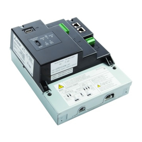
Page 6: Introduction
2. Introduction EW-50A/EW-50E is a total management system. Any connected air conditioning systems can be operated or monitored on the Web browser. EW-50A/EW-50E can also be used as an expansion controller of AE-200A/AE-200E. By connecting AE-200A/AE-200E, up to 200 indoor units and other equipment can be controlled. - Page 7 * Back side with the service cover removed LAN1 LAN2 (Unused) (Unused) (Unused) CN21 Ground Item Description IP addresses can be easily set with SW1. Refer to section 8-3 “Quick IP address setting” for details. LAN1 Connects to other units of equipment over the LAN via a HUB. LAN2 Unused CN7 (Pulse Input)
-
Page 8: Package Contents
3. Package contents The following items are included in the package. Package contents Qty. EW-50 Connector (CN6) (Unused) Connector (CN7) (Used for pulse input) L-fitting DIN rail attachment (for attaching DIN rail of 35 mm (1-7/16 in) width) DIN rail auxiliary bracket Roundhead screw (M3 ×... -
Page 9: Specifications
4. Specifications 4-1. Product specifications Item Specifications Power supply 100–240 VAC ± 10%; 50/60 Hz Single-phase M-NET power feeding coefficient Operating temperature -10°C – +55°C (+14°F – +131°F) range Temperature Ambient Storage temperature conditions -20°C – +60°C (-4°F – +140°F) range Humidity 30%–90% RH (Non-condensing) -
Page 10: External Dimensions
4-2. External dimensions (1) When using L-fittings Unit: mm (in) L-fitting (supplied) (1-8/16) 100 (3-15/16) L-fitting 169 (6-11/16) 92 (3-10/16) (supplied) 172 (6-13/16) (2) When using DIN rail 23 (15/16) 150 (5-15/16) DIN rail DIN rail attachment (supplied) DIN rail auxiliary 46 (1-13/16) bracket (supplied) -
Page 11: Product Features
4-3. Product features The table below summarizes the available functions and settings on the Web browser. Refer to the Web browser instruction books (separate volume) for details. Function Description ON/OFF The ON/OFF operation can be performed collectively or for each group or block. The operation mode can be switched collectively or for each group or block. - Page 12 Function Description Malfunction List Displays the address of the unit in error and error code. Filter sign Indicates that the filter on the unit in a given group is due for cleaning. AHC List Displays the input and output status of Advanced HVAC CONTROLLERs. Free Contact List Displays the ON/OFF status of the indoor unit free contact.
- Page 13 Function Description Back up settings data Backed-up settings data can be restored from the PC. Import settings data Backed-up settings data can be restored from a PC. Group setting information/ The group setting information and interlocked LOSSNAY information are retained in Interlocked LOSSNAY information the hardware, even if power is turned off.
-
Page 14: System Configuration
5. System configuration 5-1. System restrictions The software version of the AE-200, AE-50, and EW-50 units in a system must be the same. For details about how to update the software, refer to section 11-3 “Software update”. The restrictions vary, depending on the number of the controlled units, model of the connected units, and the functions in use. -
Page 15: M-Net Power Feeding Coefficient
5-2. M-NET power feeding coefficient The EW-50’s power feeding coefficient is 1.5. A power supply unit is not required when the power consumption coefficient of the M-NET equipment (e.g. system controller, PI controller) that will be connected to the centralized control transmission cables is 1.5 or below. Power feeding coefficient Product Power feeding coefficient... -
Page 16: System Configuration Example
5-3. System configuration example Note ● The figures in (1) through (3) below only show the transmission cable connections. Power cables are omitted. (1) When the power consumption coefficient of the M-NET equipment that will be connected to the centralized control transmission cables is 1.5 or below M-NET transmission cable Indoor unit EW-50... - Page 17 (2) When the power consumption coefficient of the M-NET equipment that will be connected to the centralized control transmission cables is greater than 1.5 Example: When two system controllers (North America: TC-24B, Europe: AT-50B) (power consumption coefficient: 1.5 each) are connected, the power consumption coefficient is 3. In this case, use a power supply unit. EW-50 Indoor unit M-NET transmission cable...
- Page 18 (3) When connecting AE-50/EW-50 controllers (up to four controllers) to an AE-200 1. When not using an apportioned electricity billing function Indoor unit Local remote controller (ME R/C type) Advanced HVAC CONTROLLER M-NET transmission cable AE-200 LAN1 IP: 192.168.1.001 LAN cable Outdoor unit (Y) [000] Numbers in parentheses indicate address...
- Page 19 2. When using an apportioned electricity billing function *1*2*3 Indoor unit AE-200 LAN1 IP: 192.168.1.001 Outdoor unit Local remote controller (ME R/C type) [000] [051] Advanced HVAC CONTROLLER TB7 TB3 [001] [002] [003] [004] M-NET transmission cable M-NET LAN cable [101] [103] Pulse signal...
-
Page 20: Number Of Connectable Units
5-4. Number of connectable units The table below summarizes the number of connectable units in an AE-200/AE-50/EW-50 M-NET system. Unit type Number of connectable units Indoor units, independent OA processing units, LOSSNAY units, DIDO controllers (PAC-YG66DCA), Air To Water (PWFY) units, Up to 50 units (including the interlocked LOSSNAY Advanced HVAC CONTROLLERs, HWHP (CAHV, CRHV) units, AI units) -
Page 21: Setting M-Net Address For Various Devices
5-5. Setting M-NET address for various devices Designate the address for each M-NET device. The addresses cannot be overlapped within the same M-NET system. Address setting method M-NET address Assign the lowest address to the main indoor unit in the group, and Indoor unit assign sequential addresses to the rest of the indoor units in the 1–50... - Page 22 [Main and Sub system controllers (M-NET)] Each group can be controlled by a Main system controller or a Sub system controller. EW-50 (AE-200/AE-50) is exclusively for use as a Main system controller and cannot be used as a Sub system controller.
-
Page 23: Installation
6. Installation Test runs, inspection, and service must be performed by qualified personnel in accordance with this manual. Incorrect use may result in injury, electric shock, malfunction, or fire. Do not install the controller where there is a risk of flammable gas leaks. If flammable gas accumulates around the controller, it may ignite and cause a fire or explosion. -
Page 24: Items Not Included
6-1. Items not included The following items are required to install the EW-50. Items not included Specifications Locknuts and bushing Must be suitable for the conduit tube to be used. M3.5 ring terminal (for AC power cables (L/L1, N/L2) and M-NET transmission cables (A, B, Sleeved ring terminal M4 ring terminal (for protective ground wire) Type: Sheathed cable (should not be lighter than ordinary sheathed cable IEC 60227.) -
Page 25: M-Net Transmission Cable Length
6-3. M-NET transmission cable length Observe the maximum total length of M-NET transmission cables to ensure proper signal transmission to and from the connected equipment over the M-NET transmission cables. If the maximum total length is exceeded, the M-NET signals will be attenuated, resulting in communication error and control failure. ●... -
Page 26: Installation Space
6-4. Installation space The EW-50 must be installed inside the metal control box. Either the supplied L-fittings or DIN rail attachments can be used for the installation. Leave a space around the EW-50 as shown in the figure below. Unit: mm (in) 50 (2) 50 (2) 50 (2) -
Page 27: Installation Procedures
6-5. Installation procedures Note ● Connect the necessary cables and wires before installing EW-50, referring to chapters 7 and 10. ● Do not install the unit where the unit may continuously receive vibration. The continuous vibration may cause the connectors to disconnect. - Page 28 6-5-2. Method 2: Installation using DIN rail 1. Have a metal control box ready. 2. Attach the supplied two DIN rail attachments to the EW-50 with the supplied roundhead screws (M3 × 12). 3. Attach the supplied DIN rail auxiliary bracket to the EW-50 with the supplied roundhead screws (M3 × 6). EW-50 DIN rail attachment (supplied)
- Page 29 [Mounting/removing the EW-50 on/from the DIN rail] Mounting Removing (1) Mounting 1. Hook the upper side of the attachments to the DIN rail. 2. Push the lower part of the EW-50 until it snaps into place. Note ● Ensure that the DIN rail attachments are fixed securely in place to the DIN rail. (2) Removing 1.
-
Page 30: Safety Notes Are Marked With Warning 7. Wiring Connections
7. Wiring connections To reduce the risk of malfunction, smoke, fire, or damage to the controller, do not connect the power cable to the signal terminal block. To reduce the risk of injury or electric shock, switch off the main power before performing electrical work. - Page 31 (2) Reinstalling 1. Insert the AC power cables and M-NET transmission cables into the openings, and then insert the hooks to the openings. Note: Do not pinch the cables between the EW-50 body and the service cover. 2. Screw down the service panel with the two fixing screws. 3.
-
Page 32: Connecting Ac Power Cables And M-Net Transmission Cables
7-2. Connecting AC power cables and M-NET transmission cables EW-50 Outdoor unit Overcurrent breaker M-NET transmission cables Earth leakage breaker for centralized control 100–240 VAC AC power cables 7-2-1. AC power cables and protective ground wire 1. Attach M3.5 sleeved ring terminals to the AC power cables, and attach an M4.0 sleeved ring terminal to the protective ground wire. - Page 33 7-2-2. M-NET transmission cables (Centralized control transmission cables) 1. Attach M3.5 sleeved ring terminals to the M-NET transmission cables (A, B, Shield). 2. Connect the M-NET transmission cables to the M-NET terminal block. 3. Fix the cables in place with the supplied cable tie. 4.
-
Page 34: Connecting The Lan Cable
7-3. Connecting the LAN cable To prevent unauthorized access, always use a security device such as a VPN router when connecting to the Internet. Connect the LAN cable to the LAN1 port on the EW-50. (The LAN2 port is unused.) ●... - Page 35 (2) Checking the transmission delay time ① Click [Start]>[Program]>[Accessories]>[Command Prompt] on the monitoring PC. ② Enter [ping (IP address of AE-200/AE-50/EW-50)], and press the Enter button. ([ping -w 1000 192.168.1.1] is entered on the sample screen below.) ③ Check that the transmission delay time that appears on the screen is 1000 ms or below. (The transmission delay time is “Maximum = 1 ms”...
-
Page 36: Initial Settings
8. Initial settings Initial settings need to be made for each EW-50 on the Web browser. Details about the initial settings and other settings and operations are covered in the Instruction Books (Web Browser for Initial Settings, Web Browser for System Maintenance Engineer). 8-1. -
Page 37: Quick Ip Address Setting
8-3. Quick IP address setting When connecting an EW-50 to a dedicated LAN system, IP address of the EW-50 can be easily set to an address between 192.168.1.1 and 192.168.1.15 with rotary switch SW1. When the IP address cannot be set with rotary switch SW1 (e.g., when connecting an EW-50 to an existing LAN, when the EW-50 is used as an expansion controller of AE-200), set the IP address on the Web browser for Initial Settings. -
Page 38: Network Settings On The Web Browser
8-4. Network settings on the Web browser IP, subnet mask, and gateway addresses can be set on the Web browser. Rotary switch SW1 must be set to “0” (default setting) to make these settings. When connecting the EW-50 to an existing LAN, consult the system administrator to decide the IP, subnet mask, and gateway addresses. -
Page 39: Test Run
9. Test run 9-1. Collective operation ON/OFF Confirm that the group settings and interlock settings are complete before performing a test run. It may take approximately five minutes from power on until the local remote controllers become operable. Refer to the indoor unit Installation Manual for details about a test run. Note: Perform a test run in the presence of a customer. -
Page 40: External Input/Output
10. External input/output 10-1. External signal input/output function To reduce the risk of injury, do not touch the burrs of the knockout holes. To use external input/output, a separately-sold external input/output adapter (PAC-YG10HA-E) is required. When connecting an external input/output adapter (PAC-YG10HA-E), cut out the CN5 knockout hole. (Refer to section 2-1 “Part names”... - Page 41 Conversely, the units that are in operation will stop when the contact turns off. Note ● Even if the Peak Cut control is not performed due to unexpected problems, Mitsubishi Electric will not be responsible for exceeding the maximum power demand.
- Page 42 (4) Pulse signal (Example) ON/OFF (Example) Prohibit/Permit 0.5–1.0 second 0.5–1.0 second Contact ON Contact ON (ON) (Prohibit) Contact OFF Contact OFF 0.5–1.0 second 0.5–1.0 second Contact ON Contact ON (OFF) (Permit) Contact OFF Contact OFF Stop Stop Permit Prohibit Permit 1.
- Page 43 10-1-2. External signal output function An ON signal is output when one or more units are in operation, and an Error signal is output when one or more units are in error. (Operation status (On/Error) of the units that are connected to each EW-50 will be output.) External output (collective) EW-50...
-
Page 44: Pulse Signal Input Function
10-2. Pulse signal input function Using pulse signals directly input from metering device such as watt-hour meter, billing data and energy management data will be obtained based on the cumulative number of pulse signal input. Note ● To input pulse signals directly from the metering device to the EW-50, use the connector connected to the EW-50. (A precision screwdriver for M1 screws is required.). -
Page 45: Maintenance
11. Maintenance 11-1. Inspection and maintenance Air conditioning units including EW-50 controllers may be damaged after long use, resulting in a performance drop or the units becoming a safety hazard. To use them safely and maximize their lives, it is recommended that a maintenance contract with a dealer or qualified personnel be signed. -
Page 46: Back Up/Import Settings Data
11-2. Back up/import settings data The settings data that have been made from the Web Browser for Initial Settings can be exported to an HDD as a backup. The exported data can be imported back to the AE-200/AE-50/EW-50 to restore the previous settings after AE-200/AE-50/EW-50 replacement. - Page 47 11-2-2. Importing settings data (1) Click the [Browse...] button to launch the explorer and browse for a file that contains the data to be imported. Select the desired file, and click [Open]. The path to the file to be imported on an HDD will appear in the [Data import source] field.
-
Page 48: Software Update
11-3. Software update The EW-50 software can be updated by using a Web browser. EW-50 PC for update 11-3-1. Preparation Follow the instructions below to change the IP address of the PC that is used for software update. Note: When the system is connected to the existing LAN, ask the system administrator for permission before changing the IP address settings and updating the software. - Page 49 (3) In the [Internet Protocol Version 4 (TCP/IPv4) Properties] window, check the radio button next to [Use the following IP address]. Enter [192.168.1.*] in the [IP address] field. (The number indicated with an asterisk must be different from the IP address of the EW-50 to be updated.) Leave [255.255.255.0] in the [Subnet mask] field as it is.
- Page 50 11-3-2. Update procedures (1) Make sure that the PC that has been set in section 11-3-1 above and the EW-50 to be updated are connected with a LAN cable. (2) Turn on the power to the EW-50, and insert a CD or USB memory device in which the update file is stored to the PC.
-
Page 51: Software Information
(9) The EW-50 will reboot after the update is complete. Check that the version that will appear on the screen is the same as the version of the update file. Also check that the version displayed on the Web browser (the Registration of Optional Functions screen, via the Web Browser for Initial Settings) is also the same. -
Page 52: Error Code List
12. Error code list Error codes and their definitions are shown below. If an error occurs, note the error code and consult your dealer. (A) indicates A-control units. 12-1. M-NET errors 0092 Version combination error 0093 System configuration change warning 0094 “Charge”... - Page 53 3601 Air system operation restricted due to filter maintenance 3602 Air system operation restricted due to damper position detecting abnormality 37** Air system operation humidity abnormality allowance - Common operand: ** 38** Air system operation humidity abnormality - Common operand: ** 4000 Electric system abnormality 40*0...
-
Page 54: Errors Between Ae-200 And Ae-50 (Ew-50)
6606 Communication error - Transmission processor communication error 6607 Communication error - No ACK return 6608 Communication error - No return of response frame 6609 Communication error 6610 Communication error 6800 Communication error - Other communication errors 6801 Communication error - V-control communication error 6810 Communication error - UR communication error 6811... - Page 55 SD and SDHC Logos are trademarks of SD-3C, LLC. Java is a registered trademark of Oracle and/or its affiliates. This equipment has been tested and found to comply with the limits for a Class B digital device, pursuant to Part 15 of the FCC Rules.
- Page 56 • Satın almış olduğunuz ürünün kullanım ömrü 10 yıldır. Bu, ürünün fonksiyonunu yerine getirebilmesi için gerekli yedek parça bulundurma süresidir. Ürünün montajı için Mitsubishi Electric Turkey Elektrik Ürünleri A.Ş. yetkili servisine / bayisine başvurunuz. Servis İstasyonları ve Yedek Parça Temini : Cihazınızın bakım, onarım ve yedek parça ihtiyaçları...
- Page 57 WT07417X01...
- Page 58 WT07417X01...
- Page 59 WT07417X01...
- Page 60 This product is designed and intended for use in the residential, commercial and light-industrial environment. The product at hand is based on the following EU regulations: • Low Voltage Directive 2006/95/EC • Electromagnetic Compatibility Directive 2004/108/EC • Restriction of Hazardous Substances 2011/65/EU Please be sure to put the contact address/telephone number on this manual before handing it to the customer.
Need help?
Do you have a question about the EW-50A and is the answer not in the manual?
Questions and answers