Advertisement
Quick Links
Air Conditioning Control System
Centralized Controller
MODEL
AE-C400
EW-C50
Installation Manual
Proper installation is important for your safety and proper functioning of the units. Thoroughly read the following safety
precautions prior to installation.
Safety notes are marked with
may result when the instructions are not followed exactly as stated.
Before installing the controller, please read this Installation Manual carefully to ensure proper operation. Retain this manual
for future reference.
1 表紙
AE-C400
WARNING or
CAUTION, depending on the severity of possible consequences that
<ORIGINAL>
EW-C50
WT09937X01
en
Advertisement

Related Manuals for Mitsubishi Electric AE-C400


Summary of Contents for Mitsubishi Electric AE-C400
- Page 1 <ORIGINAL> Air Conditioning Control System Centralized Controller MODEL AE-C400 EW-C50 Installation Manual AE-C400 EW-C50 Proper installation is important for your safety and proper functioning of the units. Thoroughly read the following safety precautions prior to installation. Safety notes are marked with...
- Page 2 2Manual Download Manual Download http://www.mitsubishielectric.com/ldg/ibim/ Go to the above website to download manuals, select model name, then choose language. Besuchen Sie die oben stehende Website, um Anleitungen herunterzuladen, wählen Sie den Modellnamen und dann die Sprache aus. Rendez-vous sur le site Web ci-dessus pour télécharger les manuels, sélectionnez le nom de modèle puis choisissez la langue. Visite el sitio web anterior para descargar manuales, seleccione el nombre del modelo y luego elija el idioma.
- Page 3 Contents Safety precautions........................5 1. Introduction ........................9 1-1. About this manual ............................. 9 1-2. Trademarks and registered trademarks....................9 1-3. About Internet connection ......................... 9 1-4. For use in the U.S............................. 9 2. Parts ..........................10 2-1. Supplied parts ............................10 2-2.
- Page 4 6-5. Connecting external devices........................59 6-5-1. External input..........................59 6-5-2. External output..........................62 6-5-3. RS-485 input (CN10) ........................64 7. Post-installation inspection ................... 66 7-1. Installation checklist ..........................66 7-2. Initial settings ............................66 8. Commissioning ....................... 67 9. Instructions to the user ....................68 10.
- Page 5 Safety precautions Safety precautions Thoroughly read the following safety precautions prior to installation. Observe these precautions carefully to ensure safety. : indicates a hazardous situation which, if not avoided, could result WARNING in death or serious injury. : indicates a hazardous situation which, if not avoided, could result CAUTION in minor or moderate injury.
- Page 6 Safety precautions If you notice any abnormality (e.g. a burning smell), stop the operation, turn off the product, and contact your dealer. Continuing the use of the product without correcting the abnormality may result in electric shock, malfunction, or fire. Properly install all required covers to keep dust and moisture out of the product.
- Page 7 Safety precautions Precautions for installation WARNING Do not install the product where there is a risk of flammable gas leaks. If flammable gas accumulates around the product, it may ignite and cause fire or explosion. To reduce the risk of short circuits, current leakage, electric shock, malfunction, smoke, or fire, do not install the product in a place exposed to water or in a condensing environment.
- Page 8 Safety precautions Use properly rated breakers (earth leakage breaker, local switch <switch + fuse that meets local electrical codes>, molded case circuit breaker, and overcurrent breaker). Use of improperly rated breakers or substitution of fuses with steel or copper wire may result in electric shock, malfunction, smoke, or fire.
- Page 9 1. Introduction 1. Introduction The AE-C/EW-C controller is a Web-based system used to monitor and control air-conditioning and refrigeration units via a Web browser. AE-C allows you to monitor and control the units from its LCD screen. 1-1. About this manual This manual explains how to install the controller.
- Page 10 2. Parts 2. Parts 2-1. Supplied parts The package contains the following. Check for any missing parts before starting installation. AE-C Item Shape Quantity Remarks AE-C — The connector is on the rear of the Connector (RS-485) controller. Used for installation except when using the Front frame mounting kit for control panel (optional part P-2).
- Page 11 2. Parts EW-C Item Shape Quantity Remarks D-11 EW-C — The connector is on the front of the Connector (RS-485) controller. D-12 Installation frame Used to install the controller. Roundhead screw (M3 x D-13 (Two Used to secure the controller. spares) Used to install the controller on a DIN rail (commercial part S-8).
- Page 12 2. Parts 2-2. Optional parts Use genuine parts specified by Mitsubishi Electric for the following parts. AE-C Item Model Quantity Remarks Electrical box PAC-YK94UTB-J Mounting kit Mounting bracket for control DIN rail attachment PAC-YK96TK-J Required to install the controller,...
- Page 13 2. Parts 2-3. Commercial parts Use the following commercial parts as necessary. AE-C Unsupplied parts Item Quantity Remarks AC power wire (protective ground As required wire) M-NET transmission cable As required Wires and cables See page for the specifications. Sleeved ring terminal As required Watt-hour meter cable...
- Page 14 2. Parts EW-C Unsupplied parts Item Quantity Remarks AC power wire (protective ground As required wire) M-NET transmission cable As required Wires and cables See page for the specifications. Sleeved ring terminal As required Watt-hour meter cable As required Screw (M4) the specifications.
- Page 15 2. Parts Specifications of commercial parts Unsupplied parts Specifications Type: Sheathed cable (designated by 60227 IEC 53) (Do not use sheathed cables lighter than ordinary IEC 60227 sheathed cables.) AC power wire/ Wire type (recommended): VCT, VVF, VVR, or equivalent Protective ground wire ...
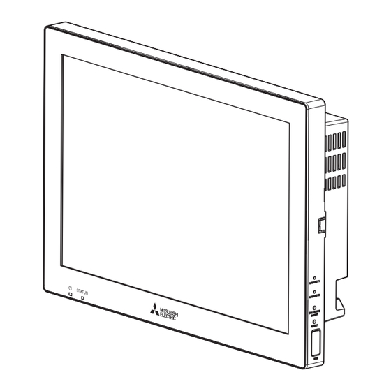
- Page 16 2. Parts 2-4. Parts names 2-4-1. AE-C AE-C (Front) Item Function and description (Bottom) Lit in green: The controller is receiving power. Unlit: The controller is not receiving power. Lit in green: On Blinking in green: Error Unlit: Off STATUS Indicates the status of the controller.
- Page 17 2. Parts Item Function and description Push switch ON/OFF Pressing the switch turns the backlight on or off. RESET Restarts the controller. (H) USB port (Type-C) (USB 3.1 Gen1) Remove the cover when connecting a device to the USB port. Leave the cover attached while not using the USB port.
- Page 18 2. Parts AE-C (Rear (without the service cover)) Item Function and description (A) LAN1 LAN port for controlling air-conditioning and refrigeration units. Connects to other AE-C or EW-C with a LAN cable via a switching HUB. (B) LAN2 LAN port for BACnet connection. Connects to a building management system with a LAN cable via a switching HUB.
- Page 19 2. Parts Item Function and description (F) TB3 (M3.5) Terminal block for connecting the M-NET transmission cable. (G) TB1 (M3.5) Terminal block for connecting the AC power wires (L/L1, N/L2). (H) Ground (M4) Terminal for connecting the protective ground wire. CN10 RS-485 connector for connecting a watt-hour meter.
- Page 20 2. Parts 2-4-2. EW-C EW-C (with the service cover) Item Function and description POWER Lit in green: The controller is receiving power. Unlit: The controller is not receiving power. ON/OFF Lit in green: On Blinking in green: Error Unlit: Off STATUS Indicates the status of the controller.
- Page 21 2. Parts Item Function and description Push switch — RESET Restarts the controller. (H) Rotary switch 0 to F Sets the IP address of LAN1 USB port (Type-C) (USB 3.1 Gen1) — Service cover To be removed when the AC power cable or M-NET transmission cable is connected to the controller.
- Page 22 2. Parts EW-C (without the service cover) Item Function and description (A) LAN1 LAN port for controlling air-conditioning and refrigeration units. Connects to other AE-C or EW-C with a LAN cable via a switching HUB. (B) LAN2 LAN port for BACnet connection. Connects to a building management system with a LAN cable via a switching HUB.
- Page 23 2. Parts Item Function and description (F) TB3 (M3.5) Terminal block for connecting the M-NET transmission cable. (G) TB1 (M3.5) Terminal block for connecting the AC power wires (L/L1, N/L2). (H) Ground (M4) Terminal for connecting the protective ground wire. CN10 RS-485 connector for connecting a watt-hour meter.
- Page 24 2. Parts 2-5. Specifications AE-C Item Specifications Power supply Rating 100-240 VAC ±10%, 50/60 Hz, single phase Power consumption 22 W LAN1, LAN2 100BASE-TX RS-485 For connecting a watt-hour meter (Modbus-RTU) Input Photocoupler input (4 inputs x 2) External input/ output Output Transistor output (2 outputs x 2) (sink type)
- Page 25 2. Parts 2-6. Notes on microSD card Do not remove the built-in microSD card. The card is exclusively for use with the controller and not for use with other devices. 2-7. Transport and unpacking WARNING Properly dispose of the packing materials. Plastic bags pose a suffocation hazard to children.
- Page 26 3. Parts location (Overview of installation) 3. Parts location (Overview of installation) 3-1. Controller parts (AE-C) *1 Wall Item Description (A) AE-C (supplied part D-1) — (B) Front frame (supplied part D-3) — (C) Rear frame (supplied part D-4) Not used when the controller is installed directly on a wall that can hold the weight of the controller (such as a gypsum-board wall), Flathead screw (M4 ×...
- Page 27 3. Parts location (Overview of installation) Note Use proper tools for installation, inspection, and repair. Use of improper tools may cause equipment damage. Do not make holes or fasten screws in areas not so specified. Prior to securing the controller, perform electrical wiring as necessary. ...
- Page 28 3. Parts location (Overview of installation) 3-2-2. Installation on a DIN rail *1 The screw holes for fastening the DIN rail attachments are indicated by arrows on the controller. *2 Screw pitch: 200 mm (7-7/8 in) max. Item Description (A) EW-C (supplied part D-11) —...
- Page 29 4. Selecting the installation site 4. Selecting the installation site 4-1. Compliance with laws and regulations Select a site that will meet the applicable laws and local regulations. 4-2. Considerations for pollution and environment contamination Select a site in consideration of minimizing pollution and environmental impact. 4-3.
- Page 30 4. Selecting the installation site 4-4. Mounting dimensions (AE-C) 4-4-1. External dimensions [1] Controller Unit: mm (in) 19.7 52.1 (25/32) (2-1/16) (12-1/16) *1 Roundhead screw (M3 x 6) [2] Mounting plate Unit: mm (in) 300 (11-13/16) 300 (11-13/16) 286 (11-9/32) 292 (11-1/2) 274 (10-13/16) 286 (11-9/32)
- Page 31 4. Selecting the installation site 4-4-2. Installation space Leave a minimum space around the controller as shown below. In particular, if the controller is located above an object (e.g., control box) with a greater depth than the controller, provide sufficient space under the controller so that the roundhead screws at the bottom of the controller can be accessed with a Phillips screwdriver.
- Page 32 4. Selecting the installation site 4-5. Mounting dimensions (EW-C) 4-5-1. External dimensions [1] Controller Unit: mm (in) 185 (7-5/16) 60.3 (2-3/8) [2] Installation on a panel inside a metal control box Unit: mm (in) 60.3 (2-3/8) 185 (7-5/16) 21.2 (27/32) (A) Installation frame (supplied part D-12) (B) Controller mounting hole WT09937X01...
- Page 33 4. Selecting the installation site [3] Installation on a DIN rail Unit: mm (in) 160 (6-5/16) 21.2 (27/32) (1-13/16) (A) DIN rail (commercial part S-8) (B) DIN rail attachment (supplied part D-14) (C) DIN rail auxiliary bracket (supplied part D-15) WT09937X01...
- Page 34 4. Selecting the installation site 4-5-2. Installation space Leave a minimum space around the controller as shown below. Unit: mm (in) (1-31/32) (1-19/32) (1-31/32) (1-31/32) (1-19/32) (1-31/32) (1-31/32) (1-31/32) 85 (3-3/8) 85 (3-3/8) (3-15/16) (3-15/16) Installation on a panel inside a metal control box Installation on a DIN rail 4-6.
- Page 35 5. Installation 5. Installation WARNING Installation work must be performed by the dealer or qualified personnel according to the instructions in the Installation Manual. Improper installation work or installation work performed by the user may cause trouble. Use the supplied or specified parts for installation. Use of improper parts may cause trouble.
- Page 36 5. Installation 5-2. Installation (AE-C) 5-2-1. Installation methods The controller can be installed in one of the following methods. For the installation methods using optional parts, refer to the Installation Manual of the optional parts. For details of the parts, refer to the specified page. "Optional parts (page 12)" "Commercial parts (page 13)" Installation methods explained in this manual Method 1 Wall-embedded installation ...
- Page 37 5. Installation Method 5 Installation on a wall that cannot be drilled (e.g., concrete wall), using a mounting attachment for wall-surface installation (PAC-YK92TB) (optional part P-3) (A) AE-C (B) Mounting attachment for wall-surface installation *1 Wall Method 6 Wall-embedded installation (Replacement of AE-200) ...
- Page 38 5. Installation 5-2-2. Preparation (for methods 1, 2, and 6) Make an installation hole (274 × 193 mm (10-13/16 × 7-5/8 in)) and mounting holes (φ6 (1/4 in) × 4) in the wall as shown in the figure below. Unit: mm (in) 286 (11-9/32) 274 (10-13/16) *1 Installation hole...
- Page 39 5. Installation Hook the top of the controller onto the two hooks of the front frame, and slide the controller down to temporarily let it hang. Fasten the controller and the front frame together, using two roundhead screws (M3 × 6) (supplied part D-7). ...
- Page 40 5. Installation [2] Installation on a metal control box Step Sandwich the metal control box (commercial part S-7) with the front frame (supplied part D-3) and the rear frame (supplied part D-4), and fasten them together, using the flathead screws (M4 × 40) (supplied part D-5). Hook the top of the controller onto the two hooks of the front frame, and slide the controller down to temporarily let it hang.
- Page 41 5. Installation 5-3. Installation (EW-C) The controller can be installed in one of the following methods. Method 1 Installation on a panel inside a metal control box (commercial part S-7) Use the installation frame (supplied part D-12). When replacing the existing EW-50 with the EW-C, the EW-C can be installed, using the existing holes.
- Page 42 5. Installation 5-3-1. Installation on a panel inside a metal control box Step Prepare a metal control box (commercial part S-7). The panel on which the controller is installed must be strong enough to hold the weight of the controller (1.9 kg (5 lbs)).
- Page 43 5. Installation 5-3-2. Installation on a DIN rail Step Prepare a metal control box (commercial part S-7). The panel on which the controller is installed must be strong enough to hold the weight of the controller (1.9 kg (5 lbs)). Fasten two DIN rail attachments (supplied part D-14) to the controller, using roundhead screws (M3 x 12) (supplied part D-16).
- Page 44 5. Installation Note Do not install the controller where it may be subjected to vibrations. To prevent the DIN rail fixing screws and the DIN rail attachments from coming into contact, do not install the DIN rail fixing screws in the areas specified in the figure below. ...
- Page 45 6. Electrical wiring 6. Electrical wiring WARNING To reduce the risk of malfunction, smoke, fire, or damage to the product, do not connect the power cable to the signal terminal block. To reduce the risk of injury or electric shock, turn off the main power before performing electrical work.
- Page 46 6. Electrical wiring 6-1. Cable connection Cables can be routed from the bottom or side of the AE-C. Cables can be routed from the side of the EW-C. To connect cables, remove the service cover. 6-2. Removing/reinstalling the service cover ...
- Page 47 6. Electrical wiring EW-C [1] Removing the service cover (A) Mounting screw (B) Service cover (C) Hook (service cover) Step Remove the mounting screws. Remove the service cover. [2] Reinstalling the service cover Before reinstalling the service cover, connect cables. For details of cable connection, refer to the specified page. "AC power cable and M-NET transmission cable (page 48)"...
- Page 48 6. Electrical wiring 6-3. AC power cable and M-NET transmission cable Connect the AC power wires (commercial part S-1), protective ground wire (commercial part S-1), and M-NET transmission wires (commercial part S-2) as shown in the figure below. Perform Class D grounding work after connecting the cables.
- Page 49 6. Electrical wiring 6-3-1. Connecting the AC power wires and the protective ground wire Before connecting the AC power cable, prepare the cable end as shown below. Attach an M3.5 sleeved ring terminal (commercial part S-3) to the AC power wires (commercial part S-1), and an M4 sleeved ring terminal (commercial part S-3) to the protective ground wire (commercial part S-1).
- Page 50 6. Electrical wiring [2] Routing the AC power cable from the bottom of the controller When routing the cable from the bottom of the controller, attach a rubber bushing (supplied part D-8) to the knockout hole. M-NET 100-240 VAC (A) Sheath (B) Cable clamp (C) Protective ground wire (commercial part S-1)
- Page 51 6. Electrical wiring EW-C M-NET 100-240 VAC (A) Sheath (B) Cable clamp (C) Protective ground wire (commercial part S-1) (D) Guide (E) AC power cable (commercial part S-1) (F) Cable clamp securing screw 100-240 VAC (G) Terminal cover *1 Route the protective ground wire between the guides to prevent it from being displaced when retightening the ground terminal.
- Page 52 6. Electrical wiring 6-3-2. Connecting the M-NET transmission wires Before connecting the M-NET transmission cable, prepare the cable end as shown below. Attach an M3.5 sleeved ring terminal (commercial part S-3) to the M-NET transmission wires (A, B, shield) (commercial part S-2). (A) Sheath 35-45 mm (1-13/32 - 1-25/32 in) (B) Sleeve...
- Page 53 6. Electrical wiring Note The M-NET transmission wire (shield) must be grounded at one point. (Class D grounding) When the M-NET power supply connector (CN21) is connected to the controller (the connector is factory- installed), the S (shield) terminal of the M-NET terminal block (TB3) will be connected to the ground terminal block inside the controller and grounded via the protective ground wire.
- Page 54 6. Electrical wiring [2] Routing the M-NET transmission cable from the bottom of the controller When routing the cable from the bottom of the controller, attach a rubber bushing (supplied part D-8) to the knockout hole. (A) Sheath (B) Cable clamp M-NET 100-240 VAC (C) M-NET transmission wire S (shield)
- Page 55 6. Electrical wiring Note When the wall thickness is 10 mm (13/32 in) or larger, route the cable through the M-NET cable hole, not through a knockout hole. The rubber bushing will come in contact with a wall having a thickness of 10 mm (13/32 in) or larger, preventing the cable from being routed.
- Page 56 6. Electrical wiring EW-C (A) Sheath (B) Cable clamp M-NET 100-240 VAC (C) M-NET transmission wire S (shield) (D) M-NET transmission wire B (non-polarized) (E) M-NET transmission wire A (non-polarized) (F) Cable clamp securing screw (G) M-NET power supply connector (CN21) (H) Terminal cover *1 Connect the cable to the outdoor unit.
- Page 57 6. Electrical wiring 6-3-3. Securing the cables To hold the cables securely, flip the cable clamp upside down to fit the thickness of the cables. On the AE-C, cables can be routed from the side or the bottom of the AE-C by changing the position of the cable clamps.
- Page 58 6. Electrical wiring 6-4. Connecting network cables Before installing the controller, complete LAN wiring work so that LAN cables can be connected to the controller. Note When monitoring air-conditioning units and other equipment via the Internet, ensure security by using security devices such as VPN router (commercial part S-22) to prevent unauthorized access and tampering.
- Page 59 6. Electrical wiring 6-5. Connecting external devices To use external inputs, external outputs, and RS-485 input, initial settings are required. For details, refer to the Instruction Book (Detailed Version) for AE-C/EW-C. 6-5-1. External input The external input function of the controller controls the connected units according to the external contact signals (12 V or 24 V DC) that are input to the controller.) An external input/output adapter (optional part P-5) is required for each controller to use the external input function.
- Page 60 6. Electrical wiring [1] Recommended circuit examples (external input) Follow the conditions below when connecting an external input circuit. Because the controller uses photocoupler input, an external power supply (12 V or 24 V DC) (commercial part S-14) is required. Because no external power supply is supplied with the controller, procure it locally. ...
- Page 61 6. Electrical wiring 2) Pulse signal (relay driving) CN5/CN6 RED: Red GRY: Gray BLU: Blue YEL: Yellow (E) (D) (C) (B) ORN: Orange AE-C/EW-C (A) External power supply (B) Input 4 (C) Input 3 (D) Input 2 (E) Input 1 ...
- Page 62 6. Electrical wiring 6-5-2. External output The external output function of the controller outputs the statuses of the units that are controlled by the controller and those controlled by other controllers (AE-C/EW-C). An external input/output adapter (optional part P-5) is required for each of the controller and other controllers (AE-C/EW-C) to use the external output function.
- Page 63 6. Electrical wiring [1] Recommended circuit examples (external output) Follow the conditions below when connecting an external output circuit. Because the controller uses transistor output (sink type), an external power supply (12 V or 24 V DC) (commercial part S-15) is required. Because no external power supply is supplied with the controller, procure it locally.
- Page 64 6. Electrical wiring 6-5-3. RS-485 input (CN10) Watt-hour meters that support RS-485 (Modbus RTU) communication can be connected to this connector to capture watt-hour data. For details on watt-hour meter settings, refer to the manual for the watt-hour meter. AE-C RS-485 (A) (B) CN10...
- Page 65 6. Electrical wiring [1] Recommended circuit examples (RS-485 input) Note To connect the watt-hour meter cable (commercial part S-4) to the connector, use a precision Phillips screwdriver (#0). (Specified torque: 0.25 N·m) Be sure to check the polarity of the terminals before connecting the cables. CN10 AE-C/EW-C *1 Watt-hour meter...
- Page 66 7. Post-installation inspection 7. Post-installation inspection After completing the installation work, perform an inspection according to the checklist below. If any problems are found, be sure to correct them to make full use of the controller and to ensure safety. After completing the inspection, make initial settings.
- Page 67 8. Commissioning 8. Commissioning Commissioning must be performed in the presence of the user. For information on the initial settings, commissioning, and software update, refer to the supplied Instruction Book or the separately available Instruction Book (Detailed Version) for AE-C/EW-C. WT09937X01...
- Page 68 9. Instructions to the user 9. Instructions to the user Provide the user with instructions for correct usage of the controller, referring to the Instruction Book. The section titled "Safety precautions" provides important safety precautions. Instruct the user to follow the precautions and instructions contained therein.
- Page 69 10. Maintenance 10. Maintenance 10-1. LCD screen and casing Wipe off dirt with a soft cloth soaked in diluted neutral detergent, and then wipe off the detergent with a dry cloth. (Dilute neutral detergent with water according to its usage instructions. Do not use undiluted detergent.) ...
- Page 72 Please be sure to put the contact address/telephone number on this manual before handing it to the customer. 872C760A10 HEAD OFFICE: TOKYO BLDG., 2-7-3, MARUNOUCHI, CHIYODA-KU, TOKYO 100-8310, JAPAN MANUFACTURER: MITSUBISHI ELECTRIC CORPORATION Air-conditioning & Refrigeration Systems Works 5-66, Tebira 6 Chome, Wakayama-city, 640-8686, Japan WT09937X01...
Need help?
Do you have a question about the AE-C400 and is the answer not in the manual?
Questions and answers