
Related Manuals for Welch Allyn Spot Vital Signs


Summary of Contents for Welch Allyn Spot Vital Signs
- Page 1 Welch Allyn Spot Vital Signs mm g mm g Spot Vital Signs Service Manual...
- Page 2 Welch Allyn. Welch Allyn assumes no responsibility for any injury to anyone, or for any illegal or improper use of the product, that may result from failure to use this product in accordance with the instructions, cautions, warnings, or statement of intended use published in this manual.
- Page 3 Front cover pages. 2012/04/26 New Material Number taken out 718448. CE mark removal Drawings and/or illustrations and/or part numbers in this document are for reference only. For the most current revision call the Welch Allyn Customer Service phone number (see page ii).
- Page 4 Welch Allyn Spot Vital Signs...
-
Page 5: Table Of Contents
Spot Vital Signs configurations ........ - Page 6 Contents Welch Allyn Spot Vital Signs 3 - Functional overview ........19 Power on/off and system check procedure .
- Page 7 Spot Vital Signs ........
- Page 8 Spot Vital Signs........
-
Page 9: Introduction
Introduction Welch Allyn has updated the Spot Vital Signs from its original configuration; offering a Pressure Preset option (Version 2, page 14) instead of a Print option (Version 1, page 13). In addition, some Version 2 configurations offer Masimo SpO technology. - Page 10 WARNING Any Spot Vital Signs which has been dropped or damaged should be checked by qualified service personnel to ensure proper operation prior to use. Do not use the Welch Allyn Spot Vital Signs if you notice any signs of damage. Contact the Welch Allyn Customer Service Department for assistance.
-
Page 11: Blood Pressure Warnings
The circumference of the child’s arm must fit within the range markings on the cuff. WARNING You may experience inaccurate blood pressure measurements if blood pressure cuffs and/or hoses other than those provided by Welch Allyn for the Spot Vital Signs are used. WARNING Patients who are experiencing moderate to severe arrhythmias may give inaccurate blood pressure measurements. -
Page 12: Spo Warnings
WARNING The SpO in the Welch Allyn Spot Vital signs is not intended for use as an apnea monitor. WARNING Consider the SpO an early warning device. As a trend toward patient deoxygenation is indicated, use laboratory instruments to analyze blood samples to completely understand the patient’s condition. -
Page 13: Temperature Warnings
IR communications port warnings WARNING The Welch Allyn Spot Vital Signs contains an infrared communications port for isolated communications with external devices. The port is located on the side of the device to preclude direct eye contact on a continual basis when viewing the display. -
Page 14: Blood Pressure Cautions
Temperature cautions Caution The Welch Allyn Spot Vital Signs is FDA cleared to measure the axillary temperature in Normal Mode for children under the age of 4. Normal Mode axillary temperatures may not be accurate on older children or adults. THE WELCH ALLYN SPOT VITAL SIGNS IS NOT INTENDED TO BE USED ON NEONATAL PATIENTS. -
Page 15: Electrostatic Discharge (Esd)
Service Manual Introduction Electrostatic discharge (ESD) Electrostatic discharge is a sudden current flowing from a charged object to another object or to ground. Electrostatic charges can accomulate on common items such as foam drinking cups, cellophane tape, synthetic clothing, untreated foam packaging material, and untreated plastic bags and work folders, to name only a few. -
Page 16: Symbols
Introduction Welch Allyn Spot Vital Signs Symbols The following symbols are associated with the Spot Vital Signs. Safety symbols Agency symbols Identifies information within the Caution: consult accompanying manual to avoid injury or equipment documents failure. Type BF Equipment Internally Powered, Lead Acid... -
Page 17: Overview
Welch Allyn’s products are available. Contact Welch Allyn Technical Service for information. Other applicable documents The Spot Vital Signs Directions for Use manual is also available. Refer to this document for information other than maintenance and repair. Welch Allyn 9600 Plus Calibration Tester Directions for Use - for all models. -
Page 18: Contents Checklist
Retain the shipping materials in the event of shipping damage or for return, if necessary, to Welch Allyn for repair or warranty service. All Spot Vital Signs include the following components: Spot Vital Signs Device. -
Page 19: Service
Center nearest you for assistance. Technical service telephone support is available on normal business days. If you are advised to return a product to Welch Allyn for repair or routine maintenance, schedule the repair with the service center nearest you. -
Page 20: Service Intervals
Overview Welch Allyn Spot Vital Signs Service intervals Verify Spot Vital Signs annually for blood pressure calibration, temperature, and SpO accuracy. Spot Vital Signs configurations Table 2. Available Versions of Spot Vital Signs Description 4200B Spot Vital Signs with blood pressure only... -
Page 21: Controls
Service Manual Overview Controls Figure 1. Spot Vital Signs with SureTemp Plus Thermometer (Version 1) Thermometer Eject Button: push to remove used temperature probe cover. Next Patient/Clear/Cancel Button: • active display: clears the display. mm g • in Standby Mode: recalls the last patient information. - Page 22 Overview Welch Allyn Spot Vital Signs Figure 2. Spot Vital Signs with SureTemp Plus Thermometer (Version 2) Thermometer Eject Button: push to remove used temperature probe cover. Next Patient/Clear/Cancel Button: • active display: clears the display. mm g • in Standby Mode: recalls the last patient information.
-
Page 23: Lcd (Liquid Crystal Display)
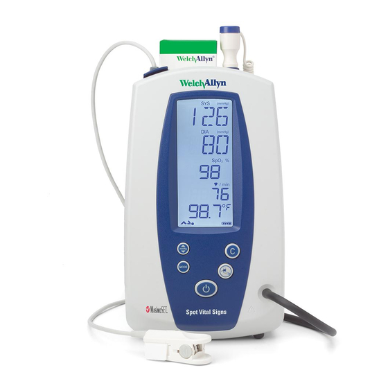
Service Manual Overview LCD (liquid crystal display) The LCD may indicate any of the following: systolic blood pressure (mmHg or kPa), diastolic blood pressure (mmHg or kPa), temperature (F or C), thermometer mode, pulse rate, pulse signal level, SpO , MAP (mmHg or kPa), and battery charge level. Option no longer available. -
Page 24: Connections
Overview Welch Allyn Spot Vital Signs Connections Use the following instructions to connect the blood pressure hose, thermometer probe, and optional attachments to the Spot Vital Signs. Figure 3. Spot Side and Rear Panel Connections Probe Cover Storage Compartment storage space for one box of probe covers. -
Page 25: Blood Pressure Hose And Cuff Connections
Spot Vital Signs one way. Verify the connector clicks into place. Insert the temperature probe into the probe holder on the top of the Spot Vital Signs. To remove the temperature probe, press down on the connector tab and lift out. -
Page 26: Dcpower Connection
Welch Allyn specified part (REF 5200-101A, 5200-103A, 5200- 103Z). Use the Spot Vital Signs with battery power (after charging the battery) or battery and DC power supply. 1. Insert the round transformer connector into the DC power connection port on the left of the Spot Vital Signs (see page 16). -
Page 27: Functional Overview
This functional verification procedure helps to confirm the proper operation of the Spot Vital Signs and options. This procedure supports the requirements of routine preventative maintenance. It is not necessary to disassemble the Spot Vital Signs to perform this procedure. -
Page 28: Internal Configuration Mode
Table 3. Configuration Menu Options Setting Description Blood Pressure Calibration Prepares the Spot Vital Signs for calibration. Only qualified personnel should verify the Displays “Cal” Spot Vital Signs blood pressure calibration. For more details, see “Blood pressure calibration” on page 27. -
Page 29: Functional Verification
Subtract the rated accuracy of the pressure measurement standard from the "3 mmHg rated accuracy of Spot Vital Signs. This is the pass/fail criteria to determine if the device is within calibration. If the differences between Spot Vital Signs and the pressure measurement standard are within the pass/fail criteria at all specified pressures, then the device is within calibration. -
Page 30: Temperature Functional Check
Functional overview Welch Allyn Spot Vital Signs NOTE: The pass/fail criteria for the blood pressure calibration check depends upon the accuracy of the pressure measurement standard used. • If the pressure measurement standard used is rated with an accuracy of ±0.1 mmHg, the pass/fail criteria is ±2.9 mmHg in order to guarantee that the instrument under... - Page 31 Service Manual Functional overview To begin functional verification of the SureTemp thermometer: Caution Store thermometers for testing in the same room as the 9600 Plus Calibration Tester for approximately 30 minutes prior to testing to allow for thermal accommodation. 1. Remove the probe from the probe well and clean it with either a 70% isopropyl alcohol solution, a 10% chlorine bleach solution, or a non-staining disinfectant.
-
Page 32: Spo2 Functional Check
RCAL Mode: RCAL63/local 2. Connect the Nellcor SpO simulator test cable to the Spot Vital Signs. 3. Verify the Spot Vital Signs reading meets the requirements of the Repair Test Specification in Appendix C. 4. Reconnect the SpO sensor. Place the sensor onto your finger and check Spot vital Signs for a reading. -
Page 33: Calibration
39 to have available during the procedures. Connections 1. Connect the blood pressure pneumatic tubing to the Spot Vital Signs and to the test station (part number 401028). 2. Connect the IR Data Interface cable to the computer. 3. Start the Spot Vital Signs repair software on the computer. - Page 34 Calibration Welch Allyn Spot Vital Signs Figure 5. Connect Diagram Part Number 401028 100 ml Vol 250 ml Vol 200 ml Vol mmHg 500 ml Vol MODE CALIBRATION MasimoSET. Spot Vital Signs...
-
Page 35: Voltage Calibration
7. Increase the pressure to 250 mmHg ±5 mmHg using the bulb and valve. 8. Use the bulb and the calibrated digital pressure meter to manually inflate the device to 200 mmHg and enter the pressure meter reading from Spot Vital Signs in the Calibration Gain text field. -
Page 36: Date/Time Set
1. Press and hold the Blood Pressure Start/Stop + Power buttons to enter the Internal Configuration mode. The Spot Vital Signs displays an E38 error. Press the C button to cancel the error, and the revision level of the internal software displays. -
Page 37: Troubleshooting
Troubleshooting When the main printed circuit board (PCB) is replaced on a Spot Vital Signs version 1, the print function is no longer available. The new function, Pressure Preset, raises or lowers the blood pressure maximum inflation level for one measurement only. When replacing the main PCB, replace the switch array as well. -
Page 38: Causes And Corrective Action
Troubleshooting Welch Allyn Spot Vital Signs Table 5. Blood Pressure Code Description Corrective Action Measurement was outside of device’s Check patient condition. measurement range Blood pressure cuff overpressure condition Check patient condition. Table 6. Temperature Code Description Corrective Action Broken/missing probe Replace probe. - Page 39 Use the correct Korotkoff sound to determine diastolic blood pressure. • Many listeners incorrectly equate diastolic blood pressure with the disappearance of sound only (phase 5). The Welch Allyn Spot Vital Signs was developed using the American Heart Association recommendations, which state that phase 5 be used unless sound continues to 0 mmHg, in which case the change in the quality of sound (phase 4) is to be used.
- Page 40 Verify the sensor cable is correctly plugged into device. Verify you are using the correct sensor. Use only Masimo or Nellcor SpO sensors and accessories with the Welch Allyn Spot Vital Signs with Masimo or Nellcor configurations, respectively. Table 13. Device Does Not Turn On...
-
Page 41: Battery Voltage Check
If an E38 error is present on Version 1, the battery does not charge correctly. Clear the error and then proceed. To charge the battery, place the battery back into the Spot Vital Signs and connect the charger for 8 hours. Let the device sit idle for one day and recheck the battery voltage. -
Page 42: Temperature Functional Check
Subtract the rated accuracy of the pressure measurement standard from the ±3 mmHg rated accuracy of Spot Vital Signs. This is the pass/fail criteria to determine if the device is within calibration. If the differences between Spot Vital Signs and the pressure measurement standard are within the pass/fail criteria at all specified pressures then the device is within calibration. -
Page 43: Current Test
“Connections” on page 25. 2. Select Test > Noise Levels in the Spot Vital Signs Repair Software and press the Test button to retrieve Spot Vital Signs internal pressure channel noise level. The test result is a pass or fail result (page 73). -
Page 44: Interface Test
8. Select off in the backlight Spot Vital Signs Repair Software to confirm the Window Display backlight goes out. 9. Select buzzer test to confirm the buzzer of Spot Vital Signs is on. Select Ok to exit the test and turn the buzzer off. -
Page 45: Pneumatic Tests
Mode button until CAL displays in the LCD window. Spot Vital Signs automatically performs an auto zero once the LCD window displays CAL. 3. Connect the Spot Vital Signs to the 500 cc cylinder and press the Blood Pressure Start/Stop button to close the valve. -
Page 46: Service Work Checklist
Troubleshooting Welch Allyn Spot Vital Signs Service work checklist Spot Vital Signs Model Number Serial Number BP Cycle Count Technician Date Test Test Data Pass/Fail Test Specification Unit SW Version SPO2 SW Version Thermometry SW Version Unit Pressure @ 0 mmHg... -
Page 47: Disassembly And Repair
Authorized Service Center. WARNING Follow the ESD procedures on see “Electrostatic discharge (ESD)” on page 7. Note Always disconnect the sealed lead-acid battery in the Spot Vital Signs before performing any repair function. Have the following tools available during the procedures. Description... -
Page 48: Battery Disassembly
Power Supply: 0-20 Vdc adjustable with 0-3A output. Battery disassembly 1. Disconnect the power and all accessories from the Spot Vital Signs. 2. Remove the four screws holding the battery door using a phillips-head screwdriver. 3. Remove the battery door to expose the battery and lift it out. Disconnect the one-way... -
Page 49: Temperature Disassembly
Temperature disassembly Follow the previous steps and then: 1. Remove the three #10 Torx screws from the temperature housing. 2. Roll the temperature housing toward the top of the Spot Vital Signs and carefully lay it on the bench. Temperature Housing Temperature PCB 3. -
Page 50: Front Housing And Key Pad Disassembly
Follow all the previous steps and then: 1. Gently lift the LCD module from the posts. 2. Roll the LCD to the left of the Spot Vital Signs and lay it on the bench. Flex Cable 3. Remove the flex cable from the LCD and set the LCD aside. -
Page 51: Power And Battery Cable Disassembly
Power and battery cable disassembly Follow all the previous steps and then: 1. Push down on the tab that connects the power cable to the main PCB and pull it toward the bottom of the Spot Vital Signs. Ferrite Bead Power cable to... -
Page 52: Main Printed Circuit Board Assembly
2. Remove the battery/valve cable connector from the bottom of the PCB. 3. Remove the 4 #10 Torx screws from the PCB. 4. Lift Main PCB from housing. If the Spot Vital Signs uses SpO then remove the three screws on the underside of the Main PCB and lift the SpO PCB off the main board (two main board connectors). -
Page 53: Spo 2 Circuit Board Disassembly
Service Manual Disassembly and repair circuit board disassembly Note To assure proper SpO operation, replace the SpO board using only the Welch Allyn specified part. To assure patient electrical isolation, after the main board is nearly back in position, verify that the SpO flex cable is freely floating and not pressed up against the main board. - Page 54 Disassembly and repair Welch Allyn Spot Vital Signs 4. Remove the 2 screws and lift the board and shielding off the standoffs. This exposes insulating paper. 5. Verify the paper is properly aligned before re-installing the shielding and the new PCB assembly.
-
Page 55: Nellcor Board
Service Manual Disassembly and repair Nellcor board Follow all the previous steps and then: 1. Remove the three phillips head screws along with the nuts and spacers from the PCB. Phillips screws Spacers (3 places) 2. Remove the SpO module (Nellcor MP205) from the main PCB. If a failure occurs in the MP205 PCB (obsolete), update to a Nell-3 PCB (704870) Note and update the Main PCB (403290). -
Page 56: Pump And Valve Disassembly
Welch Allyn Spot Vital Signs Pump and valve disassembly Note For proper blood pressure operation, replace the pump using only the Welch Allyn specifed part. To assure patient electrical isolation, do not modify the length of the pump wires. Follow all the previous steps and then: 1. - Page 57 4. Insert the elbow fitting into the 1.5 inch silicon tubing. 5. Insert the second 1.5 inch tubing onto the elbow fitting. 6. Connect the 1.5 inch tubing to the Spot Vital Signs. To assemble the pump filter: 1. Verify you have three pieces of silicon tubing .8 inches in length (421051-5), one elbow fitting (703843), one NIBP filter (600-0520-00), and one foam sleeve (706327) available.
- Page 58 Disassembly and repair Welch Allyn Spot Vital Signs 4. Carefully slide and center the foam sleeve over the NIBP filter. 5. Remove the open-ended tubing from the pump and replace with the pump filter assembly. Confirm proper pump fitting.
-
Page 59: Technical Overview
An external power supply charges the battery and can operate Spot Vital Signs at the same time. The external power supply provides the Spot Vital Signs with up to 1000mA at 7.2VDC. As the battery charges, the energy required to charge it decreases and the external power supply voltage rises to 8 VDC while supplying 750mA. -
Page 60: Mod B Nibp Power
The battery supplies power to the SpO through a +5V linear regualtor (U322). If there is no SpO module connected to the Spot Vital Signs main board the SpO2 power supply is disconnected. LCD power The main CPU supplies power to the LCD module through the J307 connector, and the FET Q312 and comparator U324A control the backlight. -
Page 61: Interconnect Diagram
Service Manual Technical overview Interconnect diagram VALVE... - Page 62 Technical overview Welch Allyn Spot Vital Signs...
-
Page 63: Field Replaceable Units
If a Version 1 (serial number less than 200705000) is sent in for updates or repair to the main printed circuit board, it is necessary to upgrade the keypad and front housing/bezel assembly. The Spot Vital Signs is then referred to and functions as a Version 2. See Table 1 on page 1 for the specific version differences. - Page 64 Field replaceable units Welch Allyn Spot Vital Signs Table 18. Spot Vital Signs Repair Parts List Description Part Number Source Rear Housing 421040-1 Welch Allyn Door, Battery 421042 Welch Allyn Pod, Temperature 421044 Welch Allyn IR Window 421045 Welch Allyn...
- Page 65 Service Manual Field replaceable units Table 18. Spot Vital Signs Repair Parts List Description Part Number Source Label, SureTemp Technology 70999-0000 Detachable Power Cord, Aust 400627 Detachable Power Cord, Swiss 761076-8 Detachable Power Cord, South America 761076-9 Foam Strip 78P567 1vb Label Blank 1”...
- Page 66 Field replaceable units Welch Allyn Spot Vital Signs Table 18. Spot Vital Signs Repair Parts List Description Part Number Source Battery, sub-assembly 421002-501 Transformer, 120VAC/60 Hz, 8 Vdc 5200-101A Transformer, 220VAC/50 Hz, 8 Vdc 5200-103A Calibration key, temperature probe calibration...
-
Page 67: Specifications
Welch Allyn defines a pediatric patient as 29 days or more of age. THE WELCH ALLYN SPOT VITAL SIGNS IS NOT INTENDED FOR USE ON NEONATES. Welch Allyn defines neonates as children 28 days or less of age, born at term (37 weeks gestation or more), otherwise up to 44 gestational weeks. -
Page 68: Pulse Pximetry
Specifications Welch Allyn Spot Vital Signs Pulse pximetry Masimo sensor accuracy guide Accuracy specified when used with Masimo SET pulse oximetry monitors or with licensed Masimo SET pulse oximetry modules using Masimo patient cables, during no motion. Numbers present ± 1 standard deviation. Plus or minus one standard deviation represents 68% of the population. -
Page 69: Nellcor® Sensor Accuracy Guide
Service Manual Specifications ® Nellcor sensor accuracy guide Accuracy specifications are based on controlled hypoxia studies with healthy, non-smoking adult volunteers over the specified saturation SpO range. Pulse oximeter readings were compared to SaO values of drawn blood samples measured by hemoximetry. -
Page 70: Nellcor Patents
A fully charged battery supports 130 typical blood pressure determinations taken at 7-minute intervals. The battery is 90-100% charged after 12 hours of charging. The battery automatically charges when the Spot Vital Signs is powered through the AC power transformer. The battery charges faster when the instrument is not in operation. -
Page 71: Guidance And Manufacturer's Declaration
Emissions and immunity information Electromagnetic Emissions The Spot Vital Signs is intended for use in the electromagnetic environment specified below. The customer or user of the Spot Vital Signs should assure that it is used in such an environment. Emissions Test... - Page 72 Welch Allyn Spot Vital Signs Electromagnetic Immunity The Spot Vital Signs is intended for use in the electromagnetic environment specified below. The customer or user of the Spot Vital Signs should assure that it is used in such an environment.
- Page 73 Service Manual Specifications Electromagnetic Immunity The Spot Vital Signs is intended for use in the electromagnetic environment specified below. The customer or user of the Spot Vital Signs should assure that it is used in such an environment. Immunity Test...
-
Page 74: Patents
Recommended Separation Distances Between Portable and Mobile RF Communications Equipment and the Spot Vital Signs The Spot Vital Signs is intended for use in an electromagnetic environment in which radiated RF disturbances are controlled. The customer or user of the Spot Vital Signs can help prevent electromagnetic interference by maintaining a minimum distance between portable and mobile RF communications equipment (transmitters) and the Spot Vital Signs as recommended below, according to the maximum output power of the communications equipment. -
Page 75: Identification Label And Serial Numbering System
Specifications Identification label and serial numbering system The identification label for the Spot Vital Signs is located on the bottom of the device. The serial number format has 9-digits. The first 4 numbers state the year of manufacture and the last 5 numbers state the Spot Vital Signs manufacturing number. Therefore, 200608000 means the 8000th Spot Vital Signs manufactured in the year 2006. - Page 76 Specifications Welch Allyn Spot Vital Signs...
-
Page 77: Maintenance
Caution Do not use ethyl alcohol to clean the Spot Vital Signs device. Caution Do not sterilize or autoclave the Spot Vital Signs. Occasionally wipe the Spot Vital Signs, as necessary, with a cloth slightly dampened with appropriately diluted, non-staining disinfectant solution. Use either 70% isopropyl alcohol, 10% chlorine bleach solution, or mild detergent in warm water. -
Page 78: Temperature Probe
2. Remove the 4 screws holding the battery door using a phillips-head screwdriver. Remove the battery door to expose the battery. 3. Tip the Spot Vital Signs to slide the battery out. Disconnect and discard the old battery per local regulations. Reconnect the new battery as shown as quickly as possible to prevent loss of power to the unit and subsequent loss of clock time. -
Page 79: Masimo Spo Calibration Check
5. Replace the battery door and tighten each of the 4 screws. 6. Connect the AC power transformer to the Spot Vital Signs and charge the new battery for 16 hours. It is possible to use the Spot Vital Signs during this charging period. - Page 80 Maintenance Welch Allyn Spot Vital Signs...
-
Page 81: A - Repair Test Specifications
250 cc cylinder from 5 mmHg to 210 mHg. The limit is 7 seconds, maximum. Dump test The Dump Test is defined as the amount of time it takes Spot Vital Signs to deflate a 500 cc cylinder from 260 mmHg to less than 15 mmHg. The limit is 10 seconds. -
Page 82: Pneumatic Calibration
Do not calibrate the Spot Vital signs if the internal temperature is greater than 89.9° F (32° C). Calibrate the Spot Vital Signs with 0 and 250 mmHg applied to the pressure port with the following algorithm: Adjust the pressure calibration offset value with the following formula. ((Last auto zero... -
Page 83: Back Light (Idle) Current Test
Verify the accuracy of the temperature module is within ±0.2° F for readings with a nomal temperature of 97.3° F (36.3° C) using a Cal Key (5200-25). Verify Spot Vital Signs can read a temperature of 96.4° F (35.8° C) and 106° F (41.1° C) within ±0.3° F/±0.2° C using a Welch Allyn 9600 Plus Calibrator. -
Page 84: Fail Safe Test
Over pressure test Verify that Spot Vital Signs can detect over pressure on the pneumatic system between 296.0 mmHg and 329 mmHg. Over 15 mmHg Verify that Spot Vital Signs can detect static pressure over 15 mmHg for 180 seconds. -
Page 85: B - Supplies And Accessories
Supplies and Accessories Latex-free blood pressure Table 1. Cuff and Bag Combination Catalog # Description Catalog # Description 5200-01 Cuff and bladder, adult, one tube 5200-10 Cuff and bladder, thigh, one tube 5200-02 Cuff and bladder, large adult, one tube 5200-03 Cuff and bladder, child, one tube Table 2. -
Page 86: Pulse Oximetry Accessories And Supplies
Supplies and Accessories Welch Allyn Spot Vital Signs Pulse oximetry accessories and supplies Masimo Table 5. Adhesive Sensors: Single-Patient Use Catalog # Description Weight Range LNCS-ADTX Adhesive Finger Sensor - Adult (20 per case) >30 kg LNCS-PDTX Adhesive Finger Sensor - Pediatric (20 per case) -
Page 87: Nellcor
3 - 40 kg Dura-Y sensor) Table 11. OxiMax Sensor Cables Catalog # Description Quantity DEC-4 extension cable, 4 ft. DEC-8 extension cable, 8 ft. * The Welch Allyn Spot Vital Signs is not intended for use on neonatal patients. -
Page 88: Temperature
Supplies and Accessories Welch Allyn Spot Vital Signs Temperature Table 12. Accessories and Supplies Catalog # Description Catalog # Description 02678-100 Oral/axillary probe (9ft./2.7M) 05031-110 Disposable probe covers (10,000 covers, 25/box) 02679-100 Rectal probe (9ft./2.7M) 06137-000 Temperature Calibration Key 05031-101... -
Page 89: Miscellaneous
Service Manual Supplies and Accessories Miscellaneous Table 15. Accessories and Supplies Catalog # Description Catalog # Description 4200-84 Lead Acid Battery 5200-101A AC Power Transformer (US/Canada/Japan)-120V, 60Hz 4200-87X* Directions for Use 5200-103A AC Power Transformer (Europe/UK) -240V, 50Hz 4200-88X* Quick Reference/Error Code Card 5200-103Z AC Power Transformer (Australia) - 240V, 50Hz 4200-155... - Page 90 Supplies and Accessories Welch Allyn Spot Vital Signs...
-
Page 91: C - Miscellaneous Mounting Accessories
Wall mount kit (REF 4200-62) Caution Attach Bracket to wall before assembling basket. See Directions for Use. Welch Allyn is NOT responsible for the integrity of any Wall or IV pole mounting interface. Welch Allyn recommends that the customer contact their Biomedical Engineering department or maintenance service to ensure professional installation, safety, and reliability of any mounting accessory. -
Page 92: Mobile Stand Kit (Ref 4200-60)
Miscellaneous Mounting Accessories Welch Allyn Spot Vital Signs Mobile stand kit (REF 4200-60) 4.25 lbs 1.93 Kg LOAD... -
Page 93: Pole Mount Accessory (Ref 4200-64)
Miscellaneous Mounting Accessories IV pole mount accessory (REF 4200-64) Caution Welch Allyn is NOT responsible for the integrity of any Wall or IV pole mounting interface. Welch Allyn recommends that the customer contact their Biomedical Engineering department or maintenance service to ensure... -
Page 94: Anti-Theft Kit (Ref 4200-70)
Miscellaneous Mounting Accessories Welch Allyn Spot Vital Signs Anti-theft kit (REF 4200-70) (1) A (1) B (1) -... -
Page 95: Transformer Mounting Plate Accessory (Ref 4200-75)
1. Align the bottom of the Spot Vital Signs with the mounting plate. Wire Clamp Plate 2. Slide the Spot Vital Signs onto the 3. Tighten the integral mounting plate and start integral screw until snug. Do screw into brass nut located on not overighten. -
Page 96: Ir Dongle Mounting Accessory (Ref 4200-170)
Miscellaneous Mounting Accessories Welch Allyn Spot Vital Signs IR dongle mounting accessory (REF 4200-170) INSTALLATION INSTRUCTIONS: Step 1 - Remove rubber base from IR dongle Step 2 - Place IR dongle into bracket clamps Step 3 - Tighten screws Step 4 - Clean side of device housing... -
Page 97: Warranty
Warranty Spot Vital Signs Welch Allyn warrants Spot Vital Signs, when new, to be free of defects in material and workmanship and to perform in accordance with manufacturer's specifications for a period of two years from the date of purchase from Welch Allyn or its authorized distributors or agents. - Page 98 Warranty Welch Allyn Spot Vital Signs...
- Page 100 Reorder No. 4200-89E Material No. 718448 Ver A...
Need help?
Do you have a question about the Spot Vital Signs and is the answer not in the manual?
Questions and answers