Advertisement
Quick Links
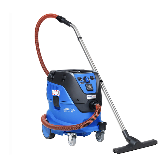
ATTIX 33/44 L + M + H
VHS 40/42 L + M + H
Service manual
Hotline: 08337 - 75301
Moltkestraße 13
R O B E
Tel.: 0 83 37 / 75 301
R e i n i g u n g s m a s c h i n e n
info@wap-nilfisk-alto-shop.de
www.wap-nilfisk-alto-shop.de
Blue line models:
ATTIX 33-01 IC
ATTIX 33-2L PC / IC - ATTIX 33-21 PC / IC
ATTIX 44-2L PC / IC - ATTIX 44-21 PC / IC
ATTIX 33-2M PC / IC - ATTIX 33-2H PC / IC
ATTIX 44-2M PC / IC - ATTIX 44-2H PC / IC
|
89281 Altenstadt-Illereichen
|
Fax 0 83 37 / 75 303
Grey line models:
VHS 40 L30 PC / IC
VHS 40 L30 LC FM IC
VHS 40 L40 LC FM IC
VHS 42 L30 MC PC / IC
VHS 42 L30 HC PC / IC
VHS 42 L40 MC PC / IC
VHS 42 L40 HC PC / IC
ENGLISH VER. 1
Advertisement

Related Manuals for Nilfisk-Advance ATTIX 33-01 IC


Summary of Contents for Nilfisk-Advance ATTIX 33-01 IC
- Page 1 ENGLISH VER. 1 Blue line models: Grey line models: ATTIX 33-01 IC VHS 40 L30 PC / IC ATTIX 33-2L PC / IC - ATTIX 33-21 PC / IC VHS 40 L30 LC FM IC ATTIX 44-2L PC / IC - ATTIX 44-21 PC / IC...
- Page 2 Index A. Safety issues B. Technical data C. Construction / function Troubleshooting E. Service / repair Spare parts G. Electrical diagrammes H. Tools...
- Page 3 Preface In this manual you will find A fault in the equipment Technical information sheets are a supplement to the spare the essentials you need to can have a number of causes. parts list until a follow-on publi- know when repairing wet and Chapter D Troubleshooting cation.
-
Page 4: Safety Issues
Safety issues Observe national safety directives and regulations For your own safety. for the electrical engineer- ing trade, in particular: IEC 60335-2-69 EN 60335-2-69 DIN VDE 105 part 1: operation of electrical power installations. DIN VDE 0701/0702: repair, modification and Repairs should only be testing of electrical installa- made by someone who has... -
Page 5: Technical Data
Technical data ATTIX 33/44Standard and L-class machines... - Page 6 Technical data ATTIX 33/44 M & H-class machines...
- Page 7 Technical data VHS 40/42 Standard and L-class machines...
- Page 8 Technical data VHS 40/42 M & H-class machines...
- Page 9 Construction Hatchback Solenoid actuator Filter cleaning system Motor unit Full tank sensor Flow sensor PCBA Buzzer alarm Control panel Control panel Motor speed control Hose diameter setting Flow/filter alarm indicator Rotary on/off switch Socket for power tools...
- Page 10 Construction Main filter element, PTFE Floater - full tank sensor for liquids Container clamp Air flow cover AntiStatic grounding clip 30 ltr container 42 ltr container...
- Page 11 Function Push&Clean - semi-automatic filter cleaning system By sealing the suction opening (1) a high negative pressure is generated inside the dirt tank. By actuating the cleaning button (2) on the suction head, an air flap is opened on backside of filter. The negative pressure inside the dirt tank is reduced very quickly and a re- versed air pulse flows through the fil-...
- Page 12 Function InfiniClean - Automatic filter cleaning system Even with extremely fine dust the automatic filter cleaning function allows you to work constantly with the same suction performance without having to manually clean the filter. A powerful reversed air pulse is activated every 15 second keeping the air flow on a high level. The air pulse is created by a solenoid connected to a piston with double-valve.
-
Page 13: Troubleshooting
Troubleshooting Motor not working with switch set to ”I” Check: - Mains voltage present? - Power cord plugged into socket? - Switch set to “I” ? Connect motor directly to Replace motor. Check if machine is working mains. Is motor working? correctly. - Page 14 Troubleshooting Motor not working with switch set to ”AUTO/TOOL” Check: - Mains voltage present? - Power cord plugged into wall socket? - Switch set to “AUTO/TOOL” ? - Load with > 60W plugged into socket? Connect motor directly to Replace motor. Check if machine is working mains.
-
Page 15: Service & Repair
Service / repair 0. Disassembly 1. Change motor unit 2. Change power cord 3. Replace rotary switch 4. Replace power socket 5. Change hatch back clamp 6. Change H-class/HEPA filter 7. Change solenoid 8. Flow sensor calibration... - Page 16 Disassembly WARNING: The upper section of the machine contains live components. Contact with live components leads to serious or even fatal injuries. Always disconnect the mains plug before disassembly. Loosen and lift the top part of the handle with a flat- headed screwdriver and unscrew the lower part of the handle (fig.1).
- Page 17 Disassembly WARNING: The upper section of the machine contains live components. Disconnect and dismount Hatch back Contact with live components leads to serious or even fatal injuries. Always disconnect the mains plug before disassembly. Unscrew the cable relief (fig.1). Disconnect the two solenoid wi- res from the grounding (fig.2) and the PCBA (fig.3).
- Page 18 Disassembly Disconnect and dismount Hatch back (continued) Dismount the hatch back by pressing the hinge in each side (fig.4).
- Page 19 Change motor unit WARNING: The upper section of the machine contains live components. Contact with live components leads to serious or even fatal injuries. Always disconnect the mains plug before disassembly. Motor connection to PCBA Motor connection to swicth Disassemble the handle, top cover, filter and hatch back as described in previous Section E.0.
- Page 20 Change power cord Disassemble the handle, top cover, filter and hatch back as described in previous Section E.0. Disconnect the wires on power cord from their connection points on switch and earth grounding (fig.1-3). Unscrew the cable relief and pull the cord out of the relief hole (fig.4). Install new power cord of same type as original.
- Page 21 Replace rotary switch WARNING: The upper section of the machine contains live components. Contact with live components leads to serious or even fatal injuries. Always disconnect the mains plug before disassembly. Disassemble the handle and top cover as described in previous Section E.0. Take off control panel and disconnect the wires on the switch (fig.1).
-
Page 22: Replace Power Socket
Replace power socket WARNING: The upper section of the machine contains live components. Contact with live components leads to serious or even fatal injuries. Always disconnect the mains plug before disassembly. Disassemble the handle and top cover as described in previous Section E.0. Take of control panel and disconnect the wires on the power socket (fig.1). - Page 23 Change hatchback clamp Disassemble the handle and top cover as descri- bed in previous Section E.0. Unscrew the two plastic covers on the hatch back (fig.1). Dismount the clamp by pressing the outer metal pin ”A” from right side (fig.2). Notice position of the spring (fig.3).
- Page 24 Change H-class/HEPA filter Open the container clamps (fig.1) and turn motor head upside down. Unscrew and remove the orange filter cover (fig.2). Take off H-class/HEPA filter and dispose it in a safe manner. WARNING: Filter might be contaminated by hazardous dust. Wear a P2 breathing mask and avoid spreading harmful dust.
- Page 25 Change solenoid WARNING: The upper section of the machine con- tains live compo- nents. Contact with live compo- nents leads to se- rious or even fatal injuries. Always disconnect mains plug before disassembly. Disassemble the handle and top cover as described in previous Section E.0.
- Page 26 Flow sensor calibration When? Flow sensor calibration should be carried out, if the PBCA or flow sensor has been changed during service. Also it is recommended to do a flow sensor calibration, if the motor unit has been replaced. Switch off the machine, disconnect the mains plug and take off handle and top cover as described in previous Section E.0.
- Page 27 Flow sensor calibration Continued Reconnect the mains plug and switch ON the machine to start the suction unit. WARNING: The upper section of the machine contains live components. Contact with live components leads to serious or even fatal injuries. Adjust/rotate the air restrictor (fig.4) until the manometer is indicating the following under pressure level: 165±5 mbar on 220-240V machines...
- Page 28 Spare parts Cabinet and controlpanel...
- Page 29 Spare parts Motor unit, floater / reed sensor, flow sensor, buz- zer, PCBA and hinge snaps...
- Page 30 Spare parts Baseplate...
- Page 31 Spare parts Filter cleaning system - PC Filter cleaning system - IC...
- Page 32 Electrical diagrammes Capacitor X2 Reed switch PCBA Motor Main switch / Speed selector Socket For 100-120V 01 PC 100-240V 40 PC 100-240V For 100-120V For 120V US 21 PC 100-240V 42 PC 100-240V...
- Page 33 Electrical diagrammes Socket Reed switch PCBA Motor Speed Main switch / Mode selector Solenoid Work instruction Work instruction 107417862 107416926 For 100-120V 01 IC 100-240V 40 IC 100-240V For 120V US For 100-120V 21 IC 100-240V 42 IC 100-240V...
- Page 34 Electrical diagrammes Socket Reed switch PCBA Motor Speed Main switch / Mode selector Hose selector Solenoid LED Air flow / Filter warning Buzzer Flow sensor Work instruction 107416926 Work instruction 107417862 For 100-120V 0M IC 100-240V 40 MC IC 100-240V...
- Page 35 Electrical diagrammes Socket Reed switch PCBA Motor Main switch / Speed Hose selector LED Air flow / Filter warning Buzzer Flow sensor Pressure sensor Work instruction Work instruction 107417862 107416926 2M PC 100-240V 42 MC PC 100-240V 2H PC 100-240V 42 HC PC 100-240V...
- Page 36 Electrical diagrammes Socket Reed switch PCBA Motor Speed Main switch / Mode selector Hose selector Solenoid LED Air flow / Filter warning Buzzer Flow sensor Pressure sensor Work instruction Work instruction 107417862 107416926 For 100-120V 2M IC 100-240V 42 HC IC 100-240V For 120V US For 100-120V 2H IC 100-240V...
- Page 37 Electrical diagrammes Wire overview...
- Page 38 Tools Manometer setting tool P/N 40434 Air restrictor setting tool P/N 62480 Callibration switch P/N 107416579...
Need help?
Do you have a question about the ATTIX 33-01 IC and is the answer not in the manual?
Questions and answers