Eaton 93E Installation And Operation Manual
15-80 kva 380/400/415 v
Hide thumbs
Also See for 93E:
- Installation manual ,
- Installation and operation manual (116 pages) ,
- Operation manual (92 pages)

Related Manuals for Eaton 93E


Summary of Contents for Eaton 93E
- Page 1 INSTALLATION AND OPERATION MANUAL Eaton 93E UPS 15-80 kVA (380/400/415 V) 614-01975-00...
- Page 2 The contents of this manual are the copyright of the publisher and may not be reproduced (even extracts) without the written approval of Eaton Corporation. Every care has been taken to ensure the accuracy of the information contained in this manual, but no liability can be accepted for any errors or omission.
-
Page 3: Table Of Contents
Eaton 93E UPS 15-80 kVA (380/400/415 V) Installation and Operation Manual Contents Contents ........................4 How to read this manual ................8 Safety-related signs ............... 8 Safety symbols ................8 1.2.1 Hazard symbols ..............8 1.2.3 Prohibited action symbols ..........9 1.2.4 Mandatory action symbols .......... - Page 4 Eaton 93E UPS 15-80 kVA (380/400/415 V) Installation and Operation Manual 4.3.3 UPS system interface wiring preparation ......45 Inspecting and unpacking the UPS cabinets ........46 UPS system installation ................49 Preliminary installation information ..........49 Unloading the UPS cabinet from the pallet ........49 External power cabling installation..........
- Page 5 Eaton 93E UPS 15-80 kVA (380/400/415 V) Installation and Operation Manual 7.3.4 Transfer from the normal mode to the bypass mode ..101 7.3.5 Transfer from the standard normal mode to the HE mode ................102 7.3.6 Transfer from the HE mode to the standard normal mode ................
- Page 6 Eaton 93E UPS 15-80 kVA (380/400/415 V) Installation and Operation Manual Product specifications ..................126 10.1 Model numbers ................126 10.2 Specifications ................127 10.2.1 Directives and standards ........... 127 10.2.2 UPS environmental ............128 10.2.3 UPS input ................128 10.2.4 UPS output ............... 129 Warranty ......................131...
-
Page 7: How To Read This Manual
Eaton 93E UPS 15-80 kVA (380/400/415 V) Installation and Operation Manual How to read this manual Safety-related signs The following table explains the safety-related signs used in this document. DANGER indicates a hazard with a high level of risk which, DANGER if not avoided, will result in serious injury or death. -
Page 8: Prohibited Action Symbols
Eaton 93E UPS 15-80 kVA (380/400/415 V) Installation and Operation Manual 1.2.3 Prohibited action symbols These symbols are used to indicate an action that should not be taken. General symbol for No smoking prohibited action Limited or restricted access 1.2.4 Mandatory action symbols These symbols are used to indicate an action that must be taken. - Page 9 Eaton 93E UPS 15-80 kVA (380/400/415 V) Installation and Operation Manual The term line-up-and-match refers to cabinets that are physically attached to the UPS, and the wiring between them is internal. The term standalone refers to cabinets that are not physically attached to the UPS, and are wired with external contractor-supplied wiring.
-
Page 10: Safety Instructions
Eaton 93E UPS 15-80 kVA (380/400/415 V) Installation and Operation Manual Safety instructions DANGER Important safety instructions! Save these instructions! This document contains important instructions that must be followed during the installation, operation and maintenance of the UPS and the batteries. - Page 11 Eaton 93E UPS 15-80 kVA (380/400/415 V) Installation and Operation Manual WARNING To reduce the risk of fire or electric shock, install the UPS in a temperature and humidity controlled, indoor environment that is free of conductive contaminants. The ambient temperature must not exceed 40 °C (104 °F).
- Page 12 Eaton 93E UPS 15-80 kVA (380/400/415 V) Installation and Operation Manual CAUTION Only qualified service personnel knowledgeable of the UPS and battery systems and the required precautions are allowed to perform installation or service work on batteries. Keep unauthorized personnel away from the equipment.
-
Page 13: Audience
Eaton 93E UPS 15-80 kVA (380/400/415 V) Installation and Operation Manual Audience The intended audience of this document is as follows: • People who plan and perform the installation of the UPS • People who use the UPS This document provides guidelines for how to check the UPS delivery and how to install and operate the UPS. -
Page 14: Environment
Eaton 93E UPS 15-80 kVA (380/400/415 V) Installation and Operation Manual Follow the precautions and only perform the described operations. Any deviation from the instructions can be dangerous to the user or cause accidental load loss. DANGER Do not open any other screws in the unit than those holding the cover plates of the MiniSlots and the MBS locking plate. -
Page 15: Using This Manual
IEC 62485-2: Safety requirements for secondary batteries and battery installations. Using this manual This manual describes how to install and operate the Eaton 93E 15-80 kVA. Read and understand the procedures described in this manual to ensure trouble-free installation and operation. In particular, be thoroughly familiar with the remote EPO procedure (see Section 7.3.13). -
Page 16: Symbols On The Ups And Accessories
Eaton 93E UPS 15-80 kVA (380/400/415 V) Installation and Operation Manual Symbols on the UPS and accessories The following are examples of symbols used on the UPS or its accessories. The symbols are used to alert you of important information. - Page 17 Eaton 93E UPS 15-80 kVA (380/400/415 V) Installation and Operation Manual Refer to the External Battery Cabinet Installation Manual for the following additional information: • Installation instructions, including site preparation, planning for installation, cabling and safety information, and detailed illustrations...
-
Page 18: Introduction To Eaton Ups
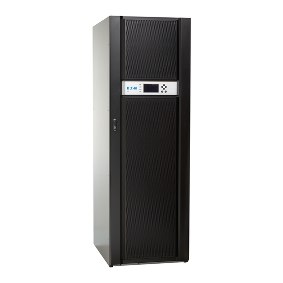
The UPS is housed in a single free-standing cabinet, with safety shields behind the door for hazardous voltage protection. This manual is for Eaton 93E series UPS, refer Section 10.1 for product models. Figure 1 shows the Eaton 93E 15-80 kVA UPS. -
Page 19: Ups Standard Features
Power cabling can be routed to the bottom or rear of the cabinet with connections made to easily accessible terminals. Some models (Eaton 93E-15I / 93E-20I / 93E-30I / 93E-40I) provide rear-only cable access. For more details, see Section 5.3. -
Page 20: Communication Interface
Chapter 8. 3.1.4 High-efficiency mode The Eaton 93E Series UPS offers a high-efficiency (HE) normal mode with double-conversion on demand. This mode allows the Eaton 93E UPS to achieve 98% efficiency while still protecting the load. For information on how to set the UPS to work in the high efficiency mode, see Chapter 7. -
Page 21: External Battery Cabinet
Eaton 93E UPS 15-80 kVA (380/400/415 V) Installation and Operation Manual 3.2.1 External battery cabinet Battery backup protection is provided by equipping the UPS system with up to 4 external battery cabinets (EBCs) containing sealed lead-acid, maintenance-free batteries. An EBC is a single, free-standing cabinet designed to be installed as a part of a UPS system, but may be installed separate from the UPS cabinet. -
Page 22: Single Feed
Installation and Operation Manual 3.2.4 Single feed The Eaton 93E 15-80 kVA standard models come with dual feed, requiring a separate feed for both rectifier and bypass input. Single feed kits are provided with each unit for on-site installation. Battery system Depending on the UPS model, the battery system may be internal or external. -
Page 23: Ups Installation Plan And Unpacking
Eaton Customer Service Engineer, or the warranty terms specified in the Warranty (see Chapter 11) become void. This service is offered as a part of the sales contract for the UPS. Contact an Eaton service representative in advance (usually a 2-week notice is required) to reserve a preferred startup date. -
Page 24: Creating An Installation Plan
Eaton 93E UPS 15-80 kVA (380/400/415 V) Installation and Operation Manual Creating an installation plan Before you install the UPS system, read and understand how these instructions apply to the system that you are going to install. Use the procedures and illustrations in Section 4.3 and Chapter 5 to create a logical plan for installing the system. -
Page 25: Parallel System Installation Checklist
Adequate lighting is provided around all the UPS equipment. A 230 VAC service outlet is located within 7.5 meters of the UPS equipment. Startup and operational checks are performed by an authorized Eaton Customer Service Engineer or by a qualified service personnel authorized by Eaton. -
Page 26: Site Preparations
Eaton 93E UPS 15-80 kVA (380/400/415 V) Installation and Operation Manual Site preparations For the UPS system to operate at peak efficiency, the installation site must meet the environmental parameters outlined in these instructions. If the UPS needs to be operated at an altitude higher than 1 000 m (3 300 ft) contact your service representative for important information about high altitude operation. - Page 27 Eaton 93E UPS 15-80 kVA (380/400/415 V) Installation and Operation Manual Mark With package Without package kg (lb.) kg (lb.) 246 (542) 207 (456) Eaton 93E-60-N-MBS 290 (639) 250 (551) Eaton 93E-80-N-MBS The UPS cabinet uses forced air cooling to regulate internal component temperature.
- Page 28 Eaton 93E UPS 15-80 kVA (380/400/415 V) Installation and Operation Manual Table 3. Eaton 93E required clearance for paralleled adjacent UPS's or UPS and adjacent PDU 15kVA/20kVA/30kVA/40kVA 60kVA/80kVA Ambient D1 (mm) D2 (mm) D1 (mm) D2 (mm) ≥120 ≥150 ≤50 ≤50...
- Page 29 Eaton 93E UPS 15-80 kVA (380/400/415 V) Installation and Operation Manual The UPS ventilation requirements are shown in Table 4. Table 4. Air conditioning or ventilation requirements during full load operation Model Input / Heat Heat output rejection rejection voltage...
- Page 30 The dimensions are in millimeters. Cable conduit inlets are illustrated with highlight. Figure 2. UPS cabinet dimensions (Eaton 93E 15-20 kVA front, rear and right side views) Figure 3. UPS cabinet dimensions (Eaton 93E 30 kVA front, rear and right side views) ©...
- Page 31 Eaton 93E UPS 15-80 kVA (380/400/415 V) Installation and Operation Manual Figure 4. UPS cabinet dimensions (Eaton 93E 40 kVA front, rear and right side views) Figure 5. UPS cabinet dimensions (Eaton 93E 60-80 kVA front, rear and right side views) ©...
- Page 32 Eaton 93E UPS 15-80 kVA (380/400/415 V) Installation and Operation Manual Figure 6. UPS cabinet dimensions (bottom and top views) Figure 7. UPS cabinet centre of gravity (Eaton 93E 15-20 kVA) without batteries © Eaton Corporation plc 2015. All rights reserved. Revision: 001...
- Page 33 Eaton 93E UPS 15-80 kVA (380/400/415 V) Installation and Operation Manual Figure 8. UPS cabinet centre of gravity (Eaton 93E 15-20 kVA) with batteries Figure 9. UPS cabinet centre of gravity (Eaton 93E 30 kVA) without batteries © Eaton Corporation plc 2015. All rights reserved.
- Page 34 Eaton 93E UPS 15-80 kVA (380/400/415 V) Installation and Operation Manual Figure 10. UPS cabinet centre of gravity (Eaton 93E 30 kVA) with batteries Figure 11. UPS cabinet centre of gravity (Eaton 93E 40 kVA) without batteries © Eaton Corporation plc 2015. All rights reserved.
- Page 35 Eaton 93E UPS 15-80 kVA (380/400/415 V) Installation and Operation Manual Figure 12. UPS cabinet centre of gravity (Eaton 93E 40 kVA) with batteries © Eaton Corporation plc 2015. All rights reserved. Revision: 001 36 (133) Document ID: 614-01975-00...
- Page 36 Eaton 93E UPS 15-80 kVA (380/400/415 V) Installation and Operation Manual Figure 13. UPS cabinet centre of gravity (Eaton 93E 60 kVA) © Eaton Corporation plc 2015. All rights reserved. Revision: 001 37 (133) Document ID: 614-01975-00...
-
Page 37: Ups System Power Cabling Preparation
Eaton 93E UPS 15-80 kVA (380/400/415 V) Installation and Operation Manual Figure 14. UPS cabinet centre of gravity (Eaton 93E 80 kVA) 4.3.2 UPS system power cabling preparation The UPS system installation must meet the following guidelines: • The system must be installed on a level floor suitable for computer or electronic equipment. - Page 38 Eaton 93E UPS 15-80 kVA (380/400/415 V) Installation and Operation Manual WARNING HIGH TOUCH CURRENT. EARTH CONNECTION ESSENTIAL BEFORE CONNECTING SUPPLY. As a result of the connected loads high leakage current is possible. Connection of the earth (ground) is required for proper product operation. Do not check UPS operation by removal of the Earth (ground) connection.
- Page 39 Eaton 93E UPS 15-80 kVA (380/400/415 V) Installation and Operation Manual • For external wiring, use a minimum of 70°C copper cable. Cable sizes listed Table 5 are for copper cable only. If cables are run in an ambient temperature greater than 30°C, higher temperature cable and/or larger size wire may be necessary.
- Page 40 Eaton 93E UPS 15-80 kVA (380/400/415 V) Installation and Operation Manual • The UPS requires an input neutral connection. Make sure that an input neutral is connected prior to energizing the UPS. If a 4-pole automatic transfer switch is installed upstream of the UPS, it must work with a break before make transition for the phase wires with a minimum transfer time of 50 ms.
- Page 41 See Table 5 for cabling recommendations. If an input/output lockable disconnect is required, it is supplied by the user. When connecting external batteries to the Eaton 93E UPS, Eaton recommends that you use the following NZM series molded case circuit...
- Page 42 Use of 4-pole breakers in the AC inputs of the UPS is not recommended. Neutral transfer must be overlapping (make-before-break). Cable lugs must be used for mounting the cabling to the UPS power cabling terminals. Table 6. UPS external power cable terminations for the Eaton 93E 15-80 kVA Tightening torque Terminal function Terminal...
- Page 43 Eaton 93E UPS 15-80 kVA (380/400/415 V) Installation and Operation Manual Rectifier input Battery output/bypass Rated Rated Fuse Rated Fuse Rated Fuse voltage current rating current rating current rating Rated power 30 kVA 380/400/415 40 kVA 380/400/415 60 kVA 380/400/415...
-
Page 44: Ups System Interface Wiring Preparation
Eaton 93E UPS 15-80 kVA (380/400/415 V) Installation and Operation Manual Battery voltage is computed at 2 volts per cell. Rated battery current is computed at 2 volts per cell. The battery cabling used between the battery and the UPS should not allow a voltage drop of more than 1% of nominal DC voltage at rated battery current. -
Page 45: Inspecting And Unpacking The Ups Cabinets
Eaton 93E UPS 15-80 kVA (380/400/415 V) Installation and Operation Manual • If you are using the power terminal wiring channel, keep the interface wiring separate from the power wiring or use shielded wire. • If using a conduit, install the interface wiring in a separate conduit from the power wiring. - Page 46 Eaton 93E UPS 15-80 kVA (380/400/415 V) Installation and Operation Manual CAUTION Do not install a damaged cabinet. Report any damage to the carrier and contact an Eaton service representative immediately. NOTE: For the following step, make sure that the forklift or pallet jack is rated to handle the weight of the cabinet (see Table 1 for cabinet weight).
- Page 47 Eaton 93E UPS 15-80 kVA (380/400/415 V) Installation and Operation Manual 3. Set the pallet on a firm, level surface, allowing a minimum clearance of 3 meters (10 feet) on each side for removing the cabinet from the pallet. 4. Remove the plastic support bands from the cardboard box.
-
Page 48: Ups System Installation
Eaton 93E UPS 15-80 kVA (380/400/415 V) Installation and Operation Manual UPS system installation Preliminary installation information The customer must supply the wiring to connect the UPS to the local power source. The electrical installation procedure is described in the following section. - Page 49 Eaton 93E UPS 15-80 kVA (380/400/415 V) Installation and Operation Manual CAUTION Do not tilt cabinet more than 10° from vertical. To prevent damages, lift the cabinets only with a forklift. NOTE: For the following steps, make sure that the forklift or pallet jack is rated to handle the weight of the cabinet (see Table 1 for cabinet weight).
- Page 50 Eaton 93E UPS 15-80 kVA (380/400/415 V) Installation and Operation Manual 3. Remove the 4 bolts that secure the front shipping bracket to the cabinet and the 4 bolts that secure the bracket to the pallet. If you are not installing the...
-
Page 51: External Power Cabling Installation
Eaton 93E UPS 15-80 kVA (380/400/415 V) Installation and Operation Manual 9. Secure the UPS cabinet in position by lowering the levelling feet until the cabinet is not resting on the casters and the cabinet is level. 10. If you are permanently mounting the system, proceed to Step 11. - Page 52 Eaton 93E UPS 15-80 kVA (380/400/415 V) Installation and Operation Manual To install wiring: Remove the dead front and back plate from the UPS. Route the cables to the UPS terminal blocks in the UPS through the cable entry point at the rear of the UPS cabinet. See Figure 15 and Figure 16 for cable access information and terminal locations.
- Page 53 Eaton 93E UPS 15-80 kVA (380/400/415 V) Installation and Operation Manual Figure 15. Power terminal locations 20-40 kVA Ground terminals AC input to UPS bypass L1 DC input from external battery + AC input to UPS bypass L2 DC input from external battery -...
- Page 54 Eaton 93E UPS 15-80 kVA (380/400/415 V) Installation and Operation Manual Figure 16 Power terminal locations 60-80 Kva Ground terminals AC output to critical load L1 AC input to UPS rectifier L1 AC output to critical load L2 AC input to UPS rectifier L2...
-
Page 55: Battery System Installation
Eaton 93E UPS 15-80 kVA (380/400/415 V) Installation and Operation Manual Battery system installation DANGER This UPS may have internal batteries. The batteries are designed to deliver a large amount of energy and an incorrect connection may lead to a short circuit and cause serious injuries to the personnel or damages to the equipment. -
Page 56: External Battery Cabinet Installation
NOTE: Do not connect external batteries to a UPS that contains internal batteries. When Eaton 93E 15-80 kVA UPS is in battery mode, the power is provided by internal or external batteries. The UPS can be equipped with up to 4 external battery cabinets (EBCs) containing valve-regulated lead- acid (VRLA), maintenance-free batteries. - Page 57 Eaton 93E UPS 15-80 kVA (380/400/415 V) Installation and Operation Manual WARNING In the event of a malfunction, the battery cabinet chassis or battery cabinet frames may become live! Take special care when working with the battery cabinet associated with the equipment. Make sure that the battery number is suited to the setting of the battery charging voltage before installing the battery.
-
Page 58: 1 + 1 Common Battery System
Ensure correct polarity! 5.4.2 1 + 1 common battery system Eaton 93E 15-80 kVA supports common battery configuration in a 1+1 redundant system containing 2 UPS's connected in parallel. The system must be configured for redundancy, meaning that the parallel system is designed to support the load up to 1 UPS capacity. -
Page 59: Installing Interface Connections
Eaton 93E UPS 15-80 kVA (380/400/415 V) Installation and Operation Manual NOTE: The common battery configuration can only be used in a system described above. Figure 18. Common battery configuration in a redundant 1+1 system UPS 1 Battery breaker UPS 2... -
Page 60: Installing Signal Input Connections
Eaton 93E UPS 15-80 kVA (380/400/415 V) Installation and Operation Manual 5.5.1 Installing signal input connections To install wiring: Make sure that the UPS system is turned off and all power sources are removed. See Chapter 7 for shutdown instructions. - Page 61 Eaton 93E UPS 15-80 kVA (380/400/415 V) Installation and Operation Manual Figure 20. Interface terminal detail (terminal cover removed) MiniSlot communication bay 2 Pull chain terminals MiniSlot communication bay 1 Parallel CAN input (RJ45) Signal inputs Parallel CAN output (RJ45) Remote EPO terminals Figure 21.
- Page 62 Eaton 93E UPS 15-80 kVA (380/400/415 V) Installation and Operation Manual Signal input Name Description terminal BA2: Signal input 2+ Input: Programmable UPS alarm, activated by a remote dry contact BA2: Signal input 2- closure. BA3: Signal input 3+ Input: Programmable UPS alarm,...
-
Page 63: Installing Parallel Wiring And Connections
Eaton 93E UPS 15-80 kVA (380/400/415 V) Installation and Operation Manual Figure 23. Communication interface cable routing for Eaton 93E 60-80 kVA Installing parallel wiring and connections To install wiring: Make sure that the UPS system is turned off and all power sources are removed. - Page 64 Make sure that each UPS static bypass and the external bypass switch (if installed) is fed from a single common source. If each UPS is fed with a separate rectifier source, consult Eaton for advice on compatibility. © Eaton Corporation plc 2015. All rights reserved.
- Page 65 Eaton 93E UPS 15-80 kVA (380/400/415 V) Installation and Operation Manual Figure 24.Parallel UPS control wiring Tie cabinet UPS 4 Terminating jumper Signal input CN9 UPS 1 Pull chain CN4 UPS 2 Twisted pairs UPS 3 Customer terminal block connections Figure 25.Parallel UPS system connections...
- Page 66 Eaton 93E UPS 15-80 kVA (380/400/415 V) Installation and Operation Manual NOTE: Module output breakers (MOBs) allow the output of a UPS to be disconnected from other UPSs and the system load for maintenance and service. Design considerations assume that each UPS has a module output breaker (MOB).
-
Page 67: Installing Minislot Interface Connections
Installing MiniSlot interface connections NOTE: The LAN drop for connection to the UPS communications card is to be supplied by the customer. For installation and setup of a MiniSlot card, contact an Eaton service representative (see Section 2.7) To install wiring: If not already installed, install the LAN drop. - Page 68 The remote EPO switch must be a normally-open or normally-closed latching-type switch that is not tied to any other circuits. This procedure is intended for installing the Eaton-supplied remote EPO switch. If you are installing another manufacturer's switch, use this procedure, and Figure 27 and Figure 28 as a guide.
- Page 69 Eaton 93E UPS 15-80 kVA (380/400/415 V) Installation and Operation Manual Table 10. Remote EPO connections Remote Description terminal Input: a normally-closed dry contact used to activate UPS EPO from a remote switch. Input: a normally-open dry contact used to activate UPS EPO from a remote switch.
- Page 70 Eaton 93E UPS 15-80 kVA (380/400/415 V) Installation and Operation Manual Figure 28.Normally-open remote EPO switch wiring Remote EPO switch (N.O.) Remote EPO TB Twisted wires Table 12. Normally-closed remote EPO wire connections Wire size From remote EPO To remote EPO...
-
Page 71: Initial Startup
Eaton. If these instructions are not followed, the warranty terms specified in Chapter 11 become void. This service is offered as a part of the sales contract for the UPS. Contact your Eaton service representative in advance to reserve a preferred startup date. -
Page 72: Understanding Ups Operation
Installation and Operation Manual Understanding UPS operation UPS system overview The Eaton 93E UPS is a continuous-duty, solid-state, 3-phase, true online system that provides conditioned and uninterruptible AC power to the UPS system's output and critical load. The basic system consists of a rectifier, battery converter, inverter, monitoring/operation control panel, integrated communication server, and digital signal processor (DSP) logic. -
Page 73: Modes
Eaton 93E UPS 15-80 kVA (380/400/415 V) Installation and Operation Manual 6.2.1 Modes The Eaton 93E UPS supports a critical load in four different modes of operation: • In the standard normal mode, the critical load is supplied by the inverter, which derives its power from rectified utility AC power. - Page 74 Eaton 93E UPS 15-80 kVA (380/400/415 V) Installation and Operation Manual Figure 30.Path of current through the UPS in the standard normal mode Static switch Bypass input Main power flow Rectifier Rectifier input Energized Inverter Output De-energized Battery Battery Trickle current...
-
Page 75: High-Efficiency Mode
Eaton 93E UPS 15-80 kVA (380/400/415 V) Installation and Operation Manual to produce a regulated and filtered AC output. The AC output of the inverter is delivered to the system output through the output relay. If the utility AC power is interrupted or is out of specification, the UPS automatically switches to the battery mode to support the critical load without interruption. - Page 76 Eaton 93E UPS 15-80 kVA (380/400/415 V) Installation and Operation Manual from the normal mode to the bypass mode manually. The bypass source supplies the commercial AC power to the load directly. Figure 31 shows the path of electrical power through the UPS system when operating in the bypass mode.
-
Page 77: Battery Mode
Eaton 93E UPS 15-80 kVA (380/400/415 V) Installation and Operation Manual protection is provided to the load but no active power conditioning or battery support is available to the output of the system in the bypass mode of operation. The internal bypass is comprised of a solid-state, silicon-controlled rectifier (SCR) continuous duty static switch, and a backfeed protection contactor. - Page 78 Eaton 93E UPS 15-80 kVA (380/400/415 V) Installation and Operation Manual Figure 32.Path of current through the UPS in standard battery mode Static switch Bypass input Main power flow Rectifier Rectifier input Energized Inverter Output De-energized Battery Battery Closed converter...
-
Page 79: Single Ups Unit System Oneline Configurations
Eaton 93E UPS 15-80 kVA (380/400/415 V) Installation and Operation Manual contactors prevent system voltages from bleeding backwards through the static switch and rectifier snubber components to the utility source. If the input power fails to return or is not within the acceptance window... - Page 80 Eaton 93E UPS 15-80 kVA (380/400/415 V) Installation and Operation Manual Figure 33.UPS system oneline diagram for Eaton 93E 15-40kVA UPS cabinet 11 AC input 21 Battery relay Internal battery (option) 12 Rectifier input switch 22 Fuse External battery cabinet 13 Fuse...
- Page 81 Eaton 93E UPS 15-80 kVA (380/400/415 V) Installation and Operation Manual Figure 34.UPS system oneline diagram for Eaton 93E 60-80kVA UPS cabinet Rectifier input switch 21 Fuse External battery cabinet 12 Fuse 22 Output relay Pull chain Rectifier input relay...
-
Page 82: Ups Operating Instructions
Eaton 93E UPS 15-80 kVA (380/400/415 V) Installation and Operation Manual UPS operating instructions This chapter describes how to operate the UPS. NOTE: Before you start the UPS, make sure that all the installation tasks are completed and a preliminary startup has been performed by authorized service personnel. - Page 83 Eaton 93E UPS 15-80 kVA (380/400/415 V) Installation and Operation Manual Figure 36.UPS switches for 15-40 kVA Neutral switch Bypass input switch Output switch Rectifier input switch Maintenance bypass switch Battery breaker (internal batteries) © Eaton Corporation plc 2015. All rights reserved.
-
Page 84: Control Panel
Eaton 93E UPS 15-80 kVA (380/400/415 V) Installation and Operation Manual Figure 37. UPS switches for 60-80 kVA Output switch Rectifier input switch Maintenance bypass switch Neutral switch Bypass input switch 7.1.1 Control panel The control panel is used to set up and control the UPS, and to monitor UPS operation. -
Page 85: Status Indicators
The following sections describe how to use the UPS control panel to monitor the UPS. When the unit powers up, the screen displays the Eaton logo as shown in Figure 38. To advance to the main menu and the Mimic screen, press any control panel push button once. -
Page 86: System Events
Eaton 93E UPS 15-80 kVA (380/400/415 V) Installation and Operation Manual Table 13. Status indicators Indicator Status Description Green symbol for normal The UPS is in the normal mode. The operation power module is supplying power to the critical load. -
Page 87: Using The Lcd And Push Buttons
Eaton 93E UPS 15-80 kVA (380/400/415 V) Installation and Operation Manual • System event horns The system event horn beeps to alert the operator that an event that requires attention is taking place. The horn cycles at a half- second rate. - Page 88 Navigation push buttons Controls Setup The UPS status area automatically scrolls between the Eaton model number, current date and time, active alarms, UPS status, load percent, and battery runtime for the UPS. When the system requires attention, the top line of the display blinks while scrolling. Some notices and alarms may be accompanied by an audible horn.
-
Page 89: Using The Menu
Eaton 93E UPS 15-80 kVA (380/400/415 V) Installation and Operation Manual You can use the LCD and the push buttons to: • Look at a log of UPS events (alarms, notices, and commands) (see Section 7.2.6) • Monitor UPS operation (see Section 7.2.6) •... -
Page 90: Mimic Screen
Eaton 93E UPS 15-80 kVA (380/400/415 V) Installation and Operation Manual 7.2.5 Mimic screen Figure 40 shows the main menu and the Mimic screen. To select the Mimic screen from the Meters, Events, History, Controls, or Setup screens, press the ESC push button on the current menu bar. - Page 91 Eaton 93E UPS 15-80 kVA (380/400/415 V) Installation and Operation Manual Function Sub-function Operation Output – UPS The Output screen shows the output voltage (phase to neutral), output current (each phase), and frequency being supplied by the UPS, as well as the kVA, kW, and power factor measurements.
- Page 92 Eaton 93E UPS 15-80 kVA (380/400/415 V) Installation and Operation Manual Function Sub-function Operation Setup – User Function This screen can be used to display user Selection information and show the installed firmware versions. Use the push buttons to select the SETUP symbol on the main menu bar to display the Setup screen.
- Page 93 Eaton 93E UPS 15-80 kVA (380/400/415 V) Installation and Operation Manual Function Sub-function Operation Function This screen can be used to set the date and Selection time, change the display language, enter a unit name, change the meter style, perform a lamp test, clear the history log, and enter a password to access level 1 functions.
- Page 94 Eaton 93E UPS 15-80 kVA (380/400/415 V) Installation and Operation Manual Function Sub-function Operation Set Date and The Set Date and Time DD/MM/YYYY Time screen allows the internal date and time of DD/MM/YYYY the UPS to be set in the day/month/year format.
- Page 95 Eaton 93E UPS 15-80 kVA (380/400/415 V) Installation and Operation Manual Function Sub-function Operation Meters The Meters Setup screen allows you to select the Meters Screen display style. Use push button to highlight Meters, then press the push button to display the Meters screen.
-
Page 96: System Controls
Eaton 93E UPS 15-80 kVA (380/400/415 V) Installation and Operation Manual Figure 41.Typical initial setup screen 7.2.7 System controls To display the Controls screen, select the CONTROLS symbol in the main menu bar and press the push button. Use the Controls screen to control the normal operation, transfer to bypass, load off, and charger control commands. - Page 97 Eaton 93E UPS 15-80 kVA (380/400/415 V) Installation and Operation Manual Table 16. Command menu operation Function Subfunction Operation UPS Control Use the push button to Commands highlight the desired command function, then press the push button to execute the command or proceed to further command screens.
-
Page 98: Single Ups Operation
Eaton 93E UPS 15-80 kVA (380/400/415 V) Installation and Operation Manual Single UPS operation NOTE: Note switch operation nomenclature: Open = O = Off Closed = I = On. Refer to the External Battery Cabinet Installation Manual for the EBC battery breaker location. -
Page 99: Starting The Ups In The Standard Normal Mode (Default Mode)
Eaton 93E UPS 15-80 kVA (380/400/415 V) Installation and Operation Manual 13. Select the CONTROLS symbol in the main menu bar. The System Control screen is displayed. 14. If not already selected, select UPS in the System Control screen. 15. In the UPS System Control screen, select the LOAD OFF →... -
Page 100: Transfer From The Bypass Mode To The Normal Mode
Eaton 93E UPS 15-80 kVA (380/400/415 V) Installation and Operation Manual 16. If requested, enter the Level 1 password. Default password is 1111. After you have entered the password, UPS transfers first to bypass and the bypass LED is illuminated. -
Page 101: Transfer From The Standard Normal Mode To The He Mode
Eaton 93E UPS 15-80 kVA (380/400/415 V) Installation and Operation Manual The bypass status indicator is illuminated. The power module remains on. WARNING Power is present inside the UPS cabinet. 7.3.5 Transfer from the standard normal mode to the HE mode To transfer the load to the HE mode: Select the CONTROLS symbol in the main menu bar. -
Page 102: Transfer From The Normal Mode To Internal Maintenance Bypass
DANGER Only service technicians are allowed to operate the neutral switch. Otherwise, keep the neutral switch closed. Only authorized Eaton Customer Service Engineers are allowed to perform the maintenance bypass operation. WARNING Power is present inside the UPS cabinet. -
Page 103: Transfer From Internal Maintenance Bypass To The Normal Mode
Eaton 93E UPS 15-80 kVA (380/400/415 V) Installation and Operation Manual 7.3.8 Transfer from internal maintenance bypass to the normal mode To transfer the load to the normal mode: Close the neutral switch, slide the cover plate over the neutral switch and tighten the screws. -
Page 104: Charger Control
Eaton 93E UPS 15-80 kVA (380/400/415 V) Installation and Operation Manual Open the UPS input and bypass feeder circuit breakers. Open all external battery breakers. 7.3.10 Charge control To turn the battery charger on: Select the CONTROLS symbol in the main menu bar. -
Page 105: 7.3.12 Using The Ups Load Off Command
Eaton 93E UPS 15-80 kVA (380/400/415 V) Installation and Operation Manual 7.3.12 Using the UPS LOAD OFF command A UPS Load Off is initiated when the Load Off command is selected in the UPS Control screen. The UPS LOAD OFF controls the UPS output by powering down the UPS and de-energizing the critical load. -
Page 106: 7.3.13 Using The Remote Emergency Power-Off Switch
Only use this feature when you want to de-energize the critical load. NOTE: The following instructions are for the Eaton-supplied remote EPO switch. If a customer-supplied remote EPO switch is used, it may not activate in the same manner. In such a case, refer to the operating instructions provided with the switch. -
Page 107: Multiple Ups Parallel Operation
Eaton 93E UPS 15-80 kVA (380/400/415 V) Installation and Operation Manual Multiple UPS parallel operation This section provides operating instructions for a UPS system containing multiple UPSs. WARNING Do not use the internal Maintenance Bypass Switch (MBS) in UPSes that are installed as a parallel system. -
Page 108: Starting The Parallel Ups In The Standard Normal Mode (Default Mode)
Eaton 93E UPS 15-80 kVA (380/400/415 V) Installation and Operation Manual 12. If not already selected, select UPS in the System Control screen. 13. In the UPS System Control screen, select the LOAD OFF → BYPASS command and press the push button. -
Page 109: Transfer From The Normal Mode To The Bypass Mode
Eaton 93E UPS 15-80 kVA (380/400/415 V) Installation and Operation Manual Once all the inverters have reached full voltage, the UPS output contactors close and the static switches turn off. The DC-link and the rectifier is turned on. The rectifier input relay closes while the DC-link continues to ramp up to full voltage. -
Page 110: Single Ups Shutdown
Eaton 93E UPS 15-80 kVA (380/400/415 V) Installation and Operation Manual In the UPS System Control screen, select the BYPASS → NORMAL command and press the push button. All of the UPSs transfer to the normal mode. If the power module is not available, the system remains on bypass and an alarm sounds. -
Page 111: Single Ups Restart
Eaton 93E UPS 15-80 kVA (380/400/415 V) Installation and Operation Manual 7.4.6 Single UPS restart To restart a single UPS from a shutdown state: Close the MOB for the UPS being restarted. Close the UPS input and bypass feeder circuit breakers for the UPS being restarted. -
Page 112: Charger Control
Eaton 93E UPS 15-80 kVA (380/400/415 V) Installation and Operation Manual Perform the LOAD OFF procedure as instructed in Section 7.4.10. The output relay and the bypass backfeed contactor open, and the power module is turned off. Perform the battery charger off procedure as instructed in Section 7.4.8 for each UPS. -
Page 113: Battery Test
Eaton 93E UPS 15-80 kVA (380/400/415 V) Installation and Operation Manual 7.4.9 Battery test NOTE: This UPS has a user initiated battery test intended to determine if the batteries are able to support the load. The battery test is only able to be initiated when the battery is fully charged. -
Page 114: 7.4.11 Using The Remote Emergency Power-Off Switch
Eaton 93E UPS 15-80 kVA (380/400/415 V) Installation and Operation Manual CAUTION All power to the critical load is lost when the LOAD OFF is selected in the following step. You should use this feature only when you want to de-energize the critical load. - Page 115 Eaton 93E UPS 15-80 kVA (380/400/415 V) Installation and Operation Manual NOTE: The following instructions are for the Eaton-supplied remote EPO switch. If a customer-supplied remote EPO switch is used, it may not activate in the same manner. Refer to the operating instructions provided with the switch.
-
Page 116: Communication
Eaton 93E UPS 15-80 kVA (380/400/415 V) Installation and Operation Manual Communication This chapter describes the communication features of the Eaton 93E UPS. For terminal wiring information, see Section 4.3.3 and Section 5.3. For location of the communication interface panel and terminals, see Figure 19 and Figure 20. -
Page 117: Signal Input Monitoring
LAN and telephone drops for use with the MiniSlot connectivity cards must be supplied by facility planners or the customer. For the installation and setup of a MiniSlot card, contact an Eaton service representative (see Section 2.7). Refer to the manual supplied with the MiniSlot card for user instructions. -
Page 118: Ups Maintenance
Eaton 93E UPS 15-80 kVA (380/400/415 V) Installation and Operation Manual UPS maintenance The components inside the UPS cabinet are secured to a sturdy metal frame. All repairable parts and assemblies are located for easy removal. This design allows authorized service personnel to perform routine maintenance and servicing quickly. -
Page 119: Performing Preventative Maintenance
Eaton 93E UPS 15-80 kVA (380/400/415 V) Installation and Operation Manual DANGER Each battery string is an energy source in itself. Do not attempt to access any internal area of the battery string yourself. Voltages are always present in the battery strings. If you suspect that a battery string needs service, contact your service representative. - Page 120 Eaton 93E UPS 15-80 kVA (380/400/415 V) Installation and Operation Manual Figure 44. Recommended preventative maintenance schedule for Eaton 93E 15- 80 kVA UPS © Eaton Corporation plc 2015. All rights reserved. Revision: 001 121 (133) Document ID: 614-01975-00...
-
Page 121: Daily Maintenance
Section 4.3.1 and Chapter 10. Check that the UPS is in the normal mode (the normal mode status indicator is illuminated). If an alarm lamp is illuminated or the normal mode status indicator is not illuminated, contact an Eaton service representative. 9.2.2... -
Page 122: Periodic Maintenance
Eaton 93E UPS 15-80 kVA (380/400/415 V) Installation and Operation Manual Figure 45. Air filter location 9.2.3 Periodic maintenance Inspect the UPS periodically to determine if components, wiring, and connections exhibit evidence of overheating. Pay particular attention to compression lug connections. During maintenance procedures, check the tightness of the compression lug connections and re-torque the connections to the values listed in this manual. -
Page 123: Installing Batteries
Eaton 93E UPS 15-80 kVA (380/400/415 V) Installation and Operation Manual Installing batteries NOTE: There is no manual DC disconnect device within the UPS for external batteries. Install batteries in accordance with the battery and battery system manufacturer's instructions. Recycling used battery or the UPS Before scrapping UPS or its battery cabinet, remove the battery bank. -
Page 124: Maintenance Training
Maintenance training A basic training course, available from Eaton Corporation, gives you a competent working knowledge of the UPS system operation and teaches you how to perform first level corrective maintenance. For more information about training and other services, contact your Eaton representative (see Section 2.7). -
Page 125: Product Specifications
Eaton 93E UPS 15-80 kVA (380/400/415 V) Installation and Operation Manual Product specifications 10.1 Model numbers The UPS is housed in a free-standing cabinet with safety shields behind the door. The UPS is available in 50 or 60 Hz with various output power ratings. -
Page 126: Specifications
Eaton 93E UPS 15-80 kVA (380/400/415 V) Installation and Operation Manual 10.2 Specifications The following sections detail the input, output, environmental, and battery specifications for the UPS. 10.2.1 Directives and standards LVD Directive 2006/95/EC on electrical Safety equipment designed for use within... -
Page 127: 10.2.2 Ups Environmental
Eaton 93E UPS 15-80 kVA (380/400/415 V) Installation and Operation Manual 10.2.2 UPS environmental 0ºC… +40ºC Operating temperature 35ºC maximum continuous 40ºC for 8 hours. Altitude temperature 40°C The recommended operating temperature is 25°C (77°F). Battery: 5 to 25°C 1 000 m above sea level at +40°C. -
Page 128: 10.2.4 Ups Output
Eaton 93E UPS 15-80 kVA (380/400/415 V) Installation and Operation Manual See Table 5, adjustable Operating input current 5% THD at full load Input current harmonic content Minimum 0.99 Power factor 6 kV OC, 3 kA SC per ANSI 62.41 and... - Page 129 Eaton 93E UPS 15-80 kVA (380/400/415 V) Installation and Operation Manual < 2% for 100% maximum load Output voltage balance imbalance (linear load) < 2.5° for 100% maximum load Output voltage phase displacement imbalance (linear load) 0.1 Hz free running Frequency regulation ±...
-
Page 130: Warranty
The warranty is only valid if the installation inspection and initial startup of the UPS unit is carried out by a service engineer approved by Eaton. Service and maintenance of the UPS shall also be performed only by a service engineer approved by Eaton. -
Page 131: Whom To Contact In Case Of Warranty
Eaton 93E UPS 15-80 kVA (380/400/415 V) Installation and Operation Manual The technical data, information and specifications are valid at the time of printing. The UPS manufacturer reserves the right to modifications without prior notice. 11.2 Whom to contact in case of Warranty... - Page 133 Eaton Power Quality Oy Koskelontie 13 FI02920 Espoo Finland www.eaton.eu...
Need help?
Do you have a question about the 93E and is the answer not in the manual?
Questions and answers