Sign In
Upload
Manuals
Brands
SpectraSensors Manuals
Measuring Instruments
SS2100
User Manuals: SpectraSensors SS2100 Gas Analyzer
Manuals and User Guides for SpectraSensors SS2100 Gas Analyzer. We have
2
SpectraSensors SS2100 Gas Analyzer manuals available for free PDF download: Hardware Installation And Maintenance Manual
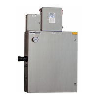
SpectraSensors SS2100 Hardware Installation And Maintenance Manual (104 pages)
H2S Analyzer
Brand:
SpectraSensors
| Category:
Measuring Instruments
| Size: 6 MB
Table of Contents
Revision History
4
Table of Contents
5
List of Figures
7
1 : Introduction
11
List of Tables
11
Who Should Read this Manual
11
How to Use this Manual
11
General Warnings and Cautions
11
Equipment Labels
12
Instructional Symbols
12
Conventions Used in this Manual
13
Spectrasensors Overview
13
About the Gas Analyzers
13
Sample Conditioning System
13
Determining Firmware Version
13
How the Analyzers Work
13
Figure 1-1 Schematic of a Typical Laser Diode Absorption Spectrometer
14
Figure 1-2 Typical Raw Signal from a Laser Diode Absorption Spectrometer with and Without Mirror Contamination
15
Differential TDLAS
16
Figure 1-3 Typical Normalized Absorption Signal from a Laser Diode Absorption Spectrometer
16
Wavelength Modulation Spectroscopy (WMS) Signal Detection
16
Getting Familiar with the Analyzer
17
Figure 1-4. Typical Normalized 2F Signal; Species
17
Figure 1-5 SS2100 Analyzer Architecture
18
Signal Terminal Block and Alarm Relays
20
Table 1-1 Fuse Specifications
21
2 : Installation
23
What Should be Included in the Shipping Box
23
Inspecting the Analyzer and SCS
23
Installing the Analyzer
23
Hardware and Tools for Installation
24
Hardware
24
Tools
24
Mounting the Analyzer
24
Lifting/Carrying the Analyzer
25
Figure 2-1. Lifting Points for the SS2100 H2S Analyzer
25
To Mount the Analyzer
26
Connecting Electrical Power to the Analyzer
26
Protective Chassis and Ground Connections
27
To Connect Electrical Power to the H S Analyzer
27
Field Interface Loads (Solenoid Valves)
28
Figure 2-2 AC Single Phase (120 VAC or 240 VAC) Connection Terminal Block in Analyzer Electronics Enclosure
29
Connecting Electrical Power to the Enclosure Heater
30
To Connect Electrical Power to the Enclosure Heater
30
Figure 2-3 AC Connection Terminal Block for 120 VAC Enclosure Heater
30
Application of Conduit Lubricant
31
Connecting the Output Signals and Alarms
32
Figure 2-4 Applying Conduit Lubricant
32
To Connect the H 2 S Analyzer Signal and Alarm Cables
33
Signal Cables
34
Changing the 4-20 Ma Current Loop Mode
35
Table 2-1 H 2 S Analyzer Input/Output Signal Connections
35
To Change the 4-20 Ma Board from Source to Sink
36
Calibrating the Analog Output
36
Figure 2-6 Analyzer 4-20 Ma Board
36
Testing and Adjusting the 4-20 Ma Zero and Span
37
Connecting the Gas Lines
37
Instrument Air
38
To Connect the Sample Supply Line
38
To Connect the Sample Return
39
To Connect the Bypass Return
40
Conditioning the SCS Tubing
41
3: Sample Conditioning System
43
About the SCS
43
Checking the SCS Installation
44
To Perform SCS Installation Checks
44
Starting up the SCS
46
To Prepare for SCS Startup
46
To Start up the Sample System Heater
46
To Start up the Field Pressure Reducing Station
47
To Start up the Sample Bypass Stream on Process Sample
47
To Start up the Analyzer on Process Sample
48
Shutting down the SCS
49
To Isolate the Measurement Cell for Short-Term Shutdown
50
To Isolate the SCS for Short-Term Shutdown
50
To Isolate the Process Sample Tap for Long-Term Shutdown
51
To Purge the Analyzer for Shipment/Relocation
52
Heat Trace Bundle Sleeve
53
Appendix A: Specifications
55
Table A-1 SS2100 H 2 S Analyzer Specifications
55
Figure A-1. Outline and Mounting Dimensions (Front View) of
57
Figure A-2. SCS Schematic of SS2100 for H S Analyzer (Fixed Mount, Conventional
58
Figure A-3. SCS Schematic - Bill of Materials (Fixed Mount, Conventional
59
Figure A-4 SCS Schematic - Solenoid/Air-Actuated Valves (Fixed Mount, Conventional)
60
Figure A-5 SCS Schematic -Air-Actuated Valve, Liquid Knock-Out (Fixed Mount, Conventional)
61
Figure A-6. SCS Schematic - High H2S Purge (Fixed Mount, Conventional
62
Figure A-7. Power and Signal Wiring Diagram (Fixed Mount, Conventional
63
Figure A-8. Wiring Diagram - Optional Air Actuated Valve (Fixed Mount, Conventional
64
Figure A-9. Outline and Mounting Dimensions - Optional Heat Trace
65
Figure A–10. Outline and Mounting Dimensions (Fixed Mount, Modular)
66
Figure A-11. SCS Schematic - Optional Heat Trace and Heater Power (Fixed Mount, Modular
67
Figure A-12. SCS Schematic - Optional One-Point Solenoid Validation (Fixed Mount, Modular
68
Figure A-13. Power and Signal Wiring (Fixed Mount, Modular
69
Spare Parts
70
Table A-2. Replacement Parts for H 2 S Analyzer
71
Appendix B: Maintenance and Troubleshooting
73
Gas Leaks
73
Contamination
73
To Keep the Sampling Lines Clean
74
Excessive Sampling Gas Temperatures and Pressures
74
Electrical Noise
75
Potential Risks Affecting Personnel
75
Mitigating Risks
75
Exposure to Process Gases
75
Exposure to Toxic Gas (H2S
75
Electrocution Hazard
76
Explosion Hazard
76
Relief Valve Setting
76
Peak Tracking Reset Procedure
76
Cleaning the Mirrors
77
Tools and Supplies
77
To Clean the Mirrors
78
Replacing the Membrane Separator
79
Replacing the Filter
80
Replacing the Pressure Sensor
80
Tools and Materials
81
To Replace the Pressure Sensor
81
Figure B-1 SCS Cabinet Interior
82
Figure B-2 Removed Measurement Cell with Pressure Sensor Face up
82
Figure B-3 Removing the Old Pressure Sensor
83
Figure B-4 Removing Excess Seal Tape from Flange
83
Figure B-5 Removing Excess Seal Tape from Inside Cell
84
Figure B-6 Replacing Seal Tape
84
Figure B-7 Replacing Pressure Sensor
85
Figure B-8 New Pressure Sensor Installed
85
Periodic SCS Maintenance
86
Preventive and On-Demand SCS Maintenance
87
Regular SCS Status Check
87
To Check Filters
88
Servicing the H 2 S Scrubber
88
Figure B-10 Scrubber and Scrubber Efficiency Indicator
89
Figure B-9. Predicted Scrubber Lifetime Based on Average H
89
After Breakthrough
90
Figure B-11 H
90
To Replace the Scrubber and Scrubber Efficiency Indicator
91
Disposal of Used Scrubbers
92
Instrument Troubleshooting
92
Table B-1 Potential Instrument Problems and Their Solutions
92
Service Contact
97
Customer Service
97
Packing
97
To Prepare the Analyzer for Shipment or Storage
98
Return Material Authorization
97
Disclaimers
99
Storage
99
Warranty
99
Index
101
Advertisement
SpectraSensors SS2100 Hardware Installation And Maintenance Manual (106 pages)
Trace Moisture Analyzer
Brand:
SpectraSensors
| Category:
Measuring Instruments
| Size: 5 MB
Table of Contents
Revision History
4
Table of Contents
5
List of Figures
9
List of Tables
11
1 : Introduction
13
How to Use this Manual
13
General Warnings and Cautions
13
Equipment Labels
13
Instructional Symbols
14
Conventions Used in this Manual
14
Who Should Read this Manual
13
About the Gas Analyzers
15
Sample Conditioning System (SCS)
15
Determining Firmware Version
15
How the Analyzers Work
15
Wavelength Modulation Spectroscopy (WMS) Signal Detection
18
Spectrasensors Overview
15
Getting Familiar with the Analyzer
19
Table 1-1 Fuse Specifications
23
2 : Installation
25
Inspecting the Analyzer
25
Installing the Analyzer
25
Hardware and Tools for Installation
26
Hardware
26
Tools
26
What Should be Included in the Shipping Box
25
Mounting the Analyzer
27
Lifting/Carrying the Analyzer
27
To Mount the Analyzer
28
Connecting Electrical Power to the Analyzer
29
Protective Chassis and Ground Connections
29
To Connect Electrical Power to the Analyzer
30
Field Interface Loads (Solenoid Valves)
31
Connecting Electrical Power to the Enclosure Heater
32
To Connect Electrical Power to the Enclosure Heater
32
Application of Conduit Lubricant
34
Connecting the Signals and Alarms
35
To Connect the Signal and Alarm Cables
36
Table 2-1 Input/Output Signal Connections
37
Changing the 4-20 Ma Current Loop Mode
38
To Change the 4-20 Ma Board from Source to Sink
38
Calibrating the Analog Output
39
Testing and Adjusting the 4-20 Ma Zero and Span
39
Connecting the Gas Lines
40
Instrument Air
40
To Connect the Sample Supply Line
40
To Connect the Sample Returns
41
To Connect the Bypass Return
42
Conditioning the SCS Tubing
43
3 : Sample Conditioning System
45
About the SCS
45
Typical SCS Component Overview
45
Sample Conditioning System Filters
46
Sample Transport Tubing
46
Sample Bypass Flow Control
46
SCS Pressure Regulator
46
Sample Flow Controller
46
Sample Dryer
47
Validation Systems
47
Sample Return/Vent
47
SCS Heaters
47
Checking the SCS Installation
48
To Perform SCS Installation Checks
48
Starting up the SCS
49
To Prepare for SCS Startup
49
To Start up the Field Pressure Reducing Station
50
To Start up the Sample Bypass Stream on Process Sample
50
To Start up the Analyzer on Process Sample
51
To Start up the Sample System Heater
52
Shutting down the SCS
52
To Isolate the Measurement Sample Cell for Short-Term Shutdown
53
To Isolate the SCS for Short-Term Shutdown
54
To Isolate the Process Sample Tap for Long-Term Shutdown
54
To Purge the Analyzer for Shipment/Relocation
56
Periodic SCS Maintenance
56
Preventive and Demand SCS Maintenance
57
Regular SCS Status Check
57
To Check Filters
58
4 : Permeation Validation
59
Validation Method
59
Permeation Validation for Trace Moisture (0-10 Ppm H O) Analyzers
59
Setting the Kp Value
60
Validation of Trace Moisture Measurements Using Permeation Devices
60
Replacing the Permeation Device
63
To Replace the Permeation Device
63
SS2100 Trace Moisture Analyzer
65
Appendix A: Specifications
65
Table A-1. SS2100 Trace Moisture Analyzer Specifications
66
Spare Parts
77
Table A-2 Replacement Parts for Trace Moisture Analyzer
77
Appendix B: Maintenance and Troubleshooting
81
Gas Leaks
81
Contamination
81
To Keep the Sampling Lines Clean
82
Excessive Sampling Gas Temperatures and Pressures
82
Electrical Noise
83
Potential Risks Affecting Personnel
83
Mitigating Risks
83
Electrocution Hazard
83
Explosion Hazard
83
Cleaning the Mirrors
84
Tools and Materials
84
To Clean the Mirrors
85
Replacing the Filter
86
Replacing the Dryer
87
Replacing a Fuse
87
Replacing the Pressure Transducer on a 8-M Cell
89
Tools and Materials
89
To Replace the Pressure Transducer on a 8-M Cell
89
Peak Tracking Reset Procedure
95
Instrument Problems
95
Table B-1 Potential Instrument Problems and Their Solutions
95
Service Contact
100
Customer Service
100
Before Contacting Technical Service
100
Service Repair Order
100
Packing
101
To Prepare the Analyzer for Shipment or Storage
101
Disclaimers
102
Storage
102
Warranty
102
Index
103
Advertisement
Related Products
SpectraSensors SS2000
Spectrasensors SS2100i-1
SpectraSensors SS500
SpectraSensors SS3000
SpectraSensors SS1000
Spectrasensors 2000 Series
SpectraSensors Categories
Measuring Instruments
Analytical Instruments
More SpectraSensors Manuals
Login
Sign In
OR
Sign in with Facebook
Sign in with Google
Upload manual
Upload from disk
Upload from URL