Table of Contents
Advertisement
Quick Links
D-304589
PG9975/PG8975/PG4975
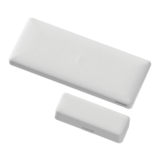
PowerG Series Wireless Door and
Window Contact Installation
Instructions
Operation
The PG9975/PG8975/PG4975 Door and Window Contacts are
fully supervised, PowerG magnetic contact devices. They
include a built-in reed switch (that opens upon removal of a
magnet placed near it). The device transmits alarm notifications
to the control panel and is supervised using the PowerG 2-way
communications protocol. The LED lights green/yellow/red,
according to signal strength, upon first insertion of the battery
and for the test period of 15 min. LED does not light while a
supervision or alarm message is being transmitted. Operating
power is obtained from an on-board 3 V Lithium battery. Built-
in link quality indicators reduce installation time by eliminating
the need for the installer to physically approach the control
panel.
Note: For UL/ULC installations use this device only in con-
junction
with
compatible
DSC
wireless
receivers:
HSM2HOST9, HS2LCDRF(P)9, HS2ICNRF(P)9 and PG9920.
Low-Battery Detection
The PGx975 includes low-battery condition detection. When
this condition is detected a trouble message is transmitted to the
compatible receiver/control panel. This will provide visual
identification of the unit that requires a battery change.
Device Setup
CAUTION!
This product uses Lithium Batteries. Improper handling of lith-
ium batteries may result in HEAT GENERATION, EXPLO-
SION or FIRE, which may lead to personal injuries.
WARNING!
DANGER
OF
EXPLOSION
IF
BATTERIES
ARE
INSTALLED INCORRECTLY. REPLACE ONLY WITH THE
SAME OR EQUIVALENT TYPE RECOMMENDED BY
THE MANUFACTURER. DISPOSE OF USED BATTERIES
ACCORDING TO THE MANUFACTURER'S INSTRUC-
TIONS
KEEP AWAY FROM SMALL CHILDREN: IF SWAL-
LOWED PROMPTLY SEE A DOCTOR.
Do not try to recharge these batteries.
Note: Installation and battery replacement should be done by
service persons in indoor non-hazardous locations only.
Note: To ensure the continued operation of all wireless devices
after performing a system default, a global upload of all wire-
less programming via DLS is recommended before defaulting
the system. After completing the system default, download the
wireless programming.
Legend
A. Enroll button
B. Battery Polarity
C. Reed switch on underside of PC Board (in unit)
D. Symbol on side of the case indicates location of reed
switch
E. Magnet
F.
1/4" space maximum (6mm)
G. Back Tamper break-away base segment (PG8975 only)
H. Mounting holes
Installing the battery
1.
Insert a 4 mm flat screwdriver into the slot of the plastic
cover, and flex the slot to open that side of the plastic
cover.
2.
Insert the screwdriver into the slot on the other side of the
plastic cover and repeat the procedure, and then remove
the cover.
3.
Insert the battery at an angle
A
while observing battery
polarity and then press down
on the battery.
Note: When manually program-
ming wireless devices, if a device
+
has been powered up for more
than 48 hours it cannot be
B
enrolled into the system until the
device has been tampered and
restored. When programming the
panel using the Quick Enroll procedure follow the steps
detailed in Enroll the Device into the System.
Note: After restoring a low battery trouble the system may take
up to 5 minutes to clear the trouble.
Enroll the Device into the System
To quick enroll:
1.
On a keypad press [*] [8] [Installer Code] [804] [000].
2.
Press and hold the device enroll button until the LED lights
steady and then release the enroll button while the LED is
still lit. A confirmation message then appears on the key-
pad.
3.
Press [*] key to confirm ID.
4.
Enter [3 digit zone #].
5.
Enter [3 digit zone type].
6.
Enter [1 digit partition #] for all desired partitions and
press [#]. If using an LCD keypad you can scroll to the
desired partitions and press [*] to toggle the partition.
7.
On an LCD keypad enter the label by using word library.
To pre-enroll:
1.
Remotely configure the unique ID number into the system.
For more information see the HSM2HOST manual.
2.
When on-site, press the device enroll button.
Note: If the wireless device has been powered for more then 48
hours without being enrolled, tamper and restore the device to
enroll it.
Mounting the Device
It is highly recommended to attach the transmitter to the top of
the door/window on the fixed frame and the magnet to the door
or window. Ensure that the magnet is located not more than 6
mm (0.25 in.) from the transmitter's marked side.
Placement Testing
Before permanently mounting any wireless device, temporarily
mount the device and perform a placement test.
1.
Tamper the device by removing the cover.
2.
Replace the cover to restore the tamper.
3.
Trip the device by opening the door or window and verify
the red LED blinks, indicating detection.
4.
After 2 seconds the LED blinks 3 times.The following
table indicates received signal strength.
LED response
Signal Strength
Green LED blinks
STRONG
Orange LED blinks
GOOD
Red LED blinks
POOR
No blinks
No communication
IMPORTANT! Only GOOD or STRONG signal strengths are
acceptable. If you receive a POOR signal from the device, re-
locate it and re-test until a GOOD or STRONG signal is
received.
Note: For UL/ULC installations, only STRONG signal levels
are acceptable. After installation verify the product functional-
ity in conjunction with the compatible receivers HSM2HOST9,
HS2LCDRF(P)9, HS2ICNRF(P)9 and PG9920.
Note: For detailed placement instructions refer to the control
panel Reference Guide.
Gap Separation
C
}
D
F
E
Z
Y
X
Metallic (Ferrous)
Nonmetallic/Metallic
Materials
(nonferrous) Materials
Direction of
Approach/
Remove/
Approach/
Remove/
Movement
Make
Break
Make
Break
of the Mag-
net
Axis X
>9mm
<12mm
>12mm
>14mm
Axis Y
>9mm
<11mm
>20mm
>22mm
Axis Z
>9mm
<12mm
>27mm
>30mm
Recommended maximum gap separation for installation (on
specified materials and axes of use) is 6mm (0.24").
Note: For EN50131-2-6 compliant installations use contact and
magnet only for axis X movement when installed on metallic
(ferrous) materials.
Mounting Procedure
Note: Adhesive tape not to be used for EU Market.
For
PG4975 and PG9975
:
1.
Peel away the release liners from the two strips of double-
sided adhesive tape and attach to the device and magnet.
2.
Align the device with the magnet according to the location
marks and fasten the device and magnet to the mounting
surface.
For PG8975:
1.
Mark and drill 2 holes in the mounting surface (3 holes for
back tamper). Fasten the base with the screws.
2.
Insert the screws.
G
Make sure that
the screw heads
are pressed
against the sur-
face of the plastic
cover and per-
pendicular to the
plastic cover.
3.
Align the device
H
with the magnet
according to the
location marks and fasten the device and magnet to the
mounting surface.
Configuration
To enter the wireless configuration section enter [804][Zone
Number].
Device Toggles
[001][04]
Supervision - Default [Y]
Enables supervision of the device.
Specifications
Frequency Band (MHz) - CE Listed PG4975: 433MHz; CE/
EN listed PG8975: 868MHz; FCC/IC/UL/ULC listed PG9975:
912-919MHz
Modulation: GFSK
Communication Protocol: PowerG
Supervision: Signaling at 256 sec. intervals
Battery: 3 V Lithium CR2032 type battery, Varta. 230mAh
Battery Life Expectancy: 5 years (not tested by UL/ULC)
Quiescent Current: 4μA
Low Battery Threshold: 2.1 V
Operating Temperature: -10ºC to +55ºC (UL only verified
the range 0º-49ºC)
Humidity: up to max. 93%RH (UL only verified up to max
85%RH)
Dimensions: (LxWxD)62 x 25.4 x 6.1 mm (2-1/2 x 1 x 1/4 in.)
Weight (including battery): 12g (0.42 oz)
Color: White or brown
Compatible Receivers
433MHz Band: HSM2HOST4; HS2LCDRF(P)4; HS2IC-
NRF(P)4; PG4920
868MHz Band: HSM2HOST8; HS2LCDRF(P)8; HS2IC-
NRF(P)8; PG8920
912-919MHz Band: HSM2HOST9; HS2LCDRF(P)9; HS2IC-
NRF(P)9; PG9920
Note: Only devices operating in band 912-919MHz are UL/
ULC listed.
Note: Only model PG9975 operating in the frequency band
912-919MHz is UL/ULC listed.
UL/ULC Notes
The PG9975 has been listed by UL/ULC for residential bur-
glary applications in accordance with the requirements in the
Standards UL 634 and ULC/ORDC634 for Door and Window
Contact.
For UL/ULC installations use this device only in conjunction
with compatible DSC wireless receivers: HSM2HOST9,
HS2LCDRF(P)9, HS2ICNRF(P)9, and PG9920.
Europe: The PG4975 and PG8975 are compliant
with the RTTE requirements - Directive 1999/5/EC
of the European Parliament and of the Council of 9
March 1999. The PG8975 is certified by Applica
Test and Certification to the following standards: EN50131-2-6,
EN50131-1 GRADE 2, CLASS II, EN50131-6 Type C.
Applica Test and Certification has certified only the 868 MHz
variant of this product. According to EN 50131-1:2006 and
A1:2009, this equipment can be applied in installed systems up
to and including Security Grade 2, Environmental Class II. UK:
The PG8975 is suitable for use in systems installed to conform
to PD6662:2010 at Grade 2 and environmental class 2 BS8243.
The Power G peripheral devices have two- way communication
functionality, providing additional benefits as described in the
technical brochure. This functionality has not been tested to
comply with the respective technical requirements and should
therefore be considered outside the scope of the product's certi-
fication.
FCC COMPLIANCE STATEMENT
WARNING! Changes or modifications to this unit not
expressly approved by the party responsible for compliance
could void the user's authority to operate the equipment.
This device has been tested and found to comply with the limits
for a Class B digital device, pursuant to Part 15 of the FCC
Rules. These limits are designed to provide reasonable protec-
tion against harmful interference in residential installations.
This equipment generates uses and can radiate radio frequency
energy and, if not installed and used in accordance with the
instructions, may cause harmful interference to radio and tele-
vision reception.
However, there is no guarantee that interference will not occur
in a particular installation. If this device does cause such inter-
ference, which can be verified by turning the device off and on,
the user is encouraged to eliminate the interference by one or
more of the following measures:
– Re-orient or re-locate the receiving antenna.
– Increase the distance between the device and the receiver.
– Connect the device to an outlet on a circuit different from the
one that supplies power to the receiver.
– Consult the dealer or an experienced radio/TV technician.
This equipment complies with FCC and IC RF radiation expo-
sure limits set forth for an uncontrolled environment.
This device complies with FCC Rules Part 15 and with Industry
Canada licence-exempt RSS standard(s). Operation is subject
to the following two conditions: (1) This device may not cause
harmful interference, and (2) this device must accept any inter-
ference that may be received or that may cause undesired oper-
ation.
Le present appareil est conforme aux CNR d'Industrie Canada
applicables aux appareils radio exempts de licence. L'exploita-
tion est autorisee aux deux conditions suivantes :(1) l'appareil
ne doit pas produire de brouillage, et (2) l'utilisateur de l'appar-
eil doit accepter tout brouillage radioelectrique subi, meme si le
brouillage est susceptible d'en compromettre le fonctionne-
ment.
PG9975/PG8975/PG4975
Instructions d'installation du con-
tact de porte et fenêtre sans fil
PowerG Series
Fonctionnement
Les contacts de porte et fenêtre PG9975/PG8975/PG4975 sont
des dispositifs à contacts magnétiques PowerG, entièrement
supervisés. Ils possèdent un commutateur à lames (qui s'ouvre à
la suite du retrait de l'aimant placé à proximité). Le dispositif
transmet les notifications d'alarme à la centrale et est supervisé
en utilisant le protocole de communication bidirectionnelle
PowerG. Le voyant lumineux s'allume en vert/jaune/rouge,
selon la force du signal, après avoir inséré la batterie et pendant
une durée de test de 15 min. Le voyant ne s'allume pas alors
qu'un message d'alarme ou de supervision est transmis. L'ali-
mentation de fonctionnement est fournie par une batterie
intégrée au lithium de 3 V. Les indicateurs de qualité de liaison
intégrés réduisent les temps d'installation en supprimant la
nécessité de l'installateur d'être physiquement à proximité de la
centrale.
Remarque : Pour les installations UL/ULC, utilisez unique-
ment ces dispositifs en association avec des récepteurs sans fil
DSC compatibles : HSM2HOST9, HS2LCDRF(P)9, HS2IC-
NRF(P)9 et PG9920.
Détection de niveau faible de batterie
Le PGx975 possède une fonction de détection de niveau faible
de batterie. Quand cet état est détecté, un message de problème
est transmis à la centrale ou au récepteur compatible. Une sig-
nalisation visuelle est ainsi assurée pour l'unité qui a besoin
d'un remplacement de batterie.
Réglage du dispositif
ATTENTION !
Ce produit utilise des batteries au lithium. La manipulation
incorrecte des piles au lithium peut engendrer UNE PRODUC-
TION DE CHALEUR, UNE EXPLOSION ou UN INCENDIE,
qui peuvent provoquer des blessures personnelles.
AVERTISSEMENT !
DANGER
D'EXPLOSION
SI
LES
PILES
SONT
INSTALLÉES DE FAÇON INCORRECTE. REMPLACEZ
UNIQUEMENT LES PILES PAR DES PILES IDENTIQUES
OU ÉQUIVALENTES, RECOMMANDÉES PAR LE FABRI-
CANT. ÉLIMINEZ LES PILES USAGÉES SELON LES
INSTRUCTIONS DE SON FABRICANT.
GARDEZ-LES HORS DE PORTÉE DES ENFANTS EN BAS
ÂGE. SI LES PILES SONT AVALÉES, CONSULTEZ
IMMÉDIATEMENT UN MÉDECIN.
N'essayez pas de recharger ces piles.
Remarque : Le remplacement et l'installation de la batterie
doivent être réalisés exclusivement par un agent de service dans
des emplacements intérieurs non dangereux.
Remarque : Pour garantir le fonctionnement continu de tous
les dispositifs sans fil après avoir réalisé une réinitialisation aux
valeurs par défaut, un téléchargement général de toute la pro-
grammation sans fil par DLS est recommandé avant de réini-
tialiser le système. Après avoir complété la réinitialisation aux
valeurs par défaut du système, téléchargez la programmation
sans fil.
Légende
A. Bouton d'attribution
B. Polarité de la batterie
C. Commutateur à lames sur le dessous du circuit imprimé
(dans l'unité)
D. Un symbole sur le côté du boîtier indique l'emplacement
du commutateur à lames
E. Aimant
F.
espace minimum de 6 mm (1/4")
G. Segment de la base amovible à contact anti-sabotage
arrière (PG8975 uniquement)
H. Trous de fixation
Installer la pile
1.
Insérez un tournevis plat de 4
A
mm dans la fente du
couvercle en plastique et
courbez légèrement la fente
pour ouvrir le côté du
couvercle en plastique.
+
2.
Insérez le tournevis dans la
fente de l'autre côté du
B
couvercle en plastique et
répétez cette opération puis
retirez le couvercle.
Advertisement
Table of Contents

Related Manuals for DSC PG9975


Summary of Contents for DSC PG9975
- Page 1 Quick Enroll procedure follow the steps Metallic (Ferrous) Nonmetallic/Metallic qu'un message d'alarme ou de supervision est transmis. L'ali- The PG9975 has been listed by UL/ULC for residential bur- Materials (nonferrous) Materials detailed in Enroll the Device into the System.
- Page 2 [*] dad del instalador de acercarse físicamente al panel de control. MHz ; PG8975 homologué CE/EN : 868 MHz ; PG9975 homo- para alternar entre particiones. Nota: Para instalaciones UL/ULC use estos dispositivos sola- logué...
- Page 3 Não tente recarregar estas baterias. pressionadas miento del Bloqueie o dispositivo removendo a tampa. Nota: Solo el modelo PG9975 que opera en la banda de fre- Nota: A instalação e a substituição da bateria devem ser real- contra a imán Volte a colocar a tampa para restaurar o bloqueio.
- Page 4 CLU, DSC refuse de Vous octroyer une licence d' u tilisation du PRODUIT LOGICIEL et Vous n' a vez pas le droit de l' u tiliser.
Need help?
Do you have a question about the PG9975 and is the answer not in the manual?
Questions and answers