Advertisement
Available languages
Available languages
Quick Links
D-304612
PG9934(P)/PG8934(P)/PG4934(P)
PowerG Wireless PIR /Pet Immune Motion
Detector with Integrated Camera Installation
Instructions
Overview
The PG9934(P)/PG8934(P)/PG4934(P) are 2-way wireless dig-
ital PIR/ Pet immune motion detectors with integrated cameras
and microphones for alarm verification. The PGx934 Series
distinguishes between human beings and pets weighing up to
38 kg (85lb) Target Specific Imaging™ and reduces false alarm
by using True Motion Recognition™.
Built-in link quality indicators reduce installation time by elim-
inating the need for the installer to physically approach the con-
trol panel.
Camera Features
• Color or black & white images
• Auto-setup for brightness and contrast via the control panel
• Day and night CMOS camera, with IR illumination. This
allows taking pictures in full darkness.
• Camera range of 12m (40ft); with IR illumination 10m
(33ft)
• Camera operation modes:
• Post alarm – pictures are taken after detection by detector.
• Optional audio with images
• Visual Verification
Notes:
1.
The camera and the listen-in feature are not to be enabled
in UL listed product.
2.
The microphone is not to be enabled in a UL listed prod-
uct.
Please be advised that this product may record and transmit
photographic images and audio recordings in the event of an
alarm condition, and that such images and recordings may be
activated remotely by a monitoring company or other third
party with authorized access to the system to which this device
is connected. It is the responsibility of the party installing and/
or monitoring the product, and or the end user, to ensure that
the installation, configuration and use of the product complies
with applicable laws, including, without limitation, laws related
to privacy, end user notifications and/or consent, posting of sig-
nage, and registration of the applicable system with local pri-
vacy authorities. To the maximum extent permitted by
applicable law, the manufacture disclaims, and shall be held
harmless and indemnified by the purchaser of this product, for
any and all liability related to compliance with such applicable
laws by the installing party, monitoring company or any third
party user of the product.
The product may be configured to limit the conditions under
which the device will record, transmit or permit remote access
to such photographic images and audio recordings.
Device Setup
Caution! Risk of explo-
sion if battery is replaced
by
an
incorrect
type.
Observe
polarity
when
installing batteries. Dis-
B
pose of used batteries
C
according to the manufac-
turer's
instructions
and
D
according to local rules
E
and regulations. Batteries
A
are to be replaced by ser-
vice persons only. To be
installed by service per-
sons
in
non-hazardous
locations only.
Note: To ensure the continued operation of all wireless devices
after performing a system default, a global upload of all wire-
less programming via DLS is recommended before defaulting
the system. After completing the system default, download the
wireless programming.
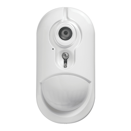
Legend
A. Microphone
B. Camera Lens
C. IR LED
D. Light Sensor
E. LEDs
F.
Battery connector
G. Cable entry knockout
H. Horizontal view
I.
Vertical view
J.
Swivel bracket Knockout
K. Mounting knockouts (for surface mounting)
L. Break-away base segment (shaded)
Caution! The back tamper switch will not protect the unit
unless the break-away base segment is secured to the wall with
at least one screw.
M. Mounting knockouts (3 of 6 – for corner mounting).
Installing Battery
1
1.
Release screw and remove
cover.
2.
Remove cover from base
3.
Position the battery in the
battery holder and insert
the battery connector ter-
minal into the battery con-
2
nector.
Note: When manually pro-
gramming wireless devices, if a
device has been powered up for
more than 48 hours it cannot be
enrolled into the system until
the device has been tampered
F
and restored. When program-
ming the panel using the Quick
Enroll procedure follow the
3
G
steps detailed in Enroll the
Device into the System.
Note: After restoring a low
battery trouble the system may
take up to 5 minutes to clear
the trouble.
Enroll the Device into
the System
To quick enroll:
1.
On a keypad press [*] [8] [Installer Code] [804] [000].
2.
Press and hold the device enroll button until the LED lights
steady and then release the enroll button while the LED is
still lit. A confirmation message then appears on the key-
pad.
3.
Press [*] key to confirm ID.
4.
Enter [3 digit zone #].
5.
Enter [3 digit zone type].
6.
Enter [1 digit partition #] for all desired partitions and
press [#]. If using an LCD keypad you can scroll to the
desired partitions and press [*] to toggle the partition.
7.
On an LCD keypad enter the label by using word library.
To pre-enroll:
1.
Remotely configure the unique ID number into the system.
For more information see the HSM2HOST manual.
2.
When on-site, press the device enroll button.
Note: If the wireless device has been powered for more than 48
hours without being enrolled, tamper and restore the device to
enroll it.
Perform a placement test
Before permanently mounting any wireless device, temporarily
mount the device and perform a Placement test.
1.
Tamper the device
9 (30ft)
by opening the
6 (20ft)
90°
cover.
H
2.
Restore the tam-
3 (10ft)
per. The device
now enters Place-
0
ment test mode.
3 (10ft)
3.
Trip the device and
the red LED blinks
6 (20ft)
once to identify
9 (30ft)
that a signal is
0
3
6
9
12 m
10
20
30
40 ft
being sent to the
I
receiver and then
2.4 m
(8 ft)
blinks three times
to identify the sig-
0
3
6
9
12 m
nal strength. To
10
20
30
40 ft
perform a walk
test, walk across
the far end of coverage pattern in both directions. The fol-
lowing table indicates received signal strength indication.
LED response
Signal Strength
Green LED blinks
STRONG
Orange LED blinks
GOOD
Red LED blinks
POOR
No blinks
No communication
IMPORTANT! Only GOOD or STRONG signal strengths are
acceptable. If you receive a POOR signal from the device, re-
locate it and re-test until a GOOD or STRONG signal is
received.
Note: For UL/ULC installations, only STRONG signal levels
are acceptable. After installation verify the product functional-
ity in conjunction with the compatible receivers HSM2HOST9,
HS2LCDRF(P)9, HS2ICNRF(P)9 and PG9920.
Note: For detailed Placement instructions refer to the control
panel Reference Guide.
Mount the Device
The PowerG Series wireless PIR Motion detectors shall be
installed and used within an environment that provides the pol-
lution degree max 2 and overvoltages category II. The equip-
ment is designed to be installed only by service persons in non-
hazardous locations only.
Note: Pet immunity feature has not been verified by UL/ULC.
• Keep away from heat sources.
• Do not expose to air drafts.
• Do not install outdoors.
• Avoid direct sunshine.
• Keep wiring away from power cables.
• Do not install behind partitions.
• Mount on solid stable surface.
• Installed in accordance with NEC, NFPA 70.
• Installed in accordance with UL 681, Standard for Installa-
tions and Classifications of burglar and Holdup Alarm Sys-
tems.
• Installed in accordance with C22.1, Canadian Electrical
Code, Part I, Safety Standard for Electrical Installations.
• Mount the detector so that its orientation is perpendicular to
the expected intrusion path.
• For installations of detector at 2m high, Dead zone is 2ft at
0m high and 0.5ft at 1.5m high.
Important! The PGx934P detector is immune to activity below
1 m (3ft) from 38 kg (85 lb) animals. Above the 1 m (3 ft)
height limit, the detector is immune to 19 kg (42 lb) animals.
Pet immunity decreases as the animal gets closer to the detec-
tor. Select a mounting location that minimizes potential close
proximity of animals.
WARNING! To comply with FCC and IC RF exposure compli-
ance requirements, the PIR detector should be located at a dis-
tance of at least 20 cm from all persons during normal
operation. The antennas used for this product must not be co-
located or operated in conjunction with any other antenna or
transmitter.
1
J
2
M
K
L
1.
Press the base against the wall at the selected mounting
position and mark the drilling points through the mounting
holes.
2.
Drill 2 holes or 3 holes (for back tamper) and attach the
base to the wall using the supplied screws.
3.
Align the cover with the base and secure with screw.
Configuration
To enter the wireless configuration section enter [804][3 digit
zone #].
Device Toggles
[001][01] Alarm LED - Default [Y]
Enables the devices LED to activate when an alarm
event occurs.
[001][04]
Supervision - Default [Y]
Enables supervision of the device.
Device Options
[003] Hightraffic Shutdown - Default [01]
Activating this feature helps conserve battery power
when the system is disarmed by configuring a reporting
timer. When motion is detected, the device transmits an
alarm to the receiver and will not report any further
events until the timer expires. Any motion detected
during the configured period will be reported once the
timer expires. No Delay causes the device to report an
alarm each time the detector is tripped.
[01] Detector
[02] No Delay
[03] 5 second
Disabled (while
delay
disarmed)
[04] 15 second
[05] 30 second
[06] 1m delay
delay
delay
[07] 5m delay
[08] 10m delay
[09] 20m delay
[10] 60m delay
[004] Image Brightness - Default [04]
Lightens and darkens the image.
[01] Image Bright
[02] Image Bright
[03] Image Bright
-3
-2
-1
[04] Image Bright
[05] Image Bright
[06] Image Bright
0
+1
+2
[07] Image Bright
+3
[005] Image Contrast - Default [04]
Lightens and darkens the contrast.
[01] Image Con-
[02] Image Con-
[03] Image Con-
trast -3
trast -2
trast -1
[04] Image Con-
[05] Image Con-
[06] Image Con-
trast 0
trast +1
trast +2
[07] Image Con-
trast +3
[011] Camera Toggles
[01] Color -
[02] High Res. -
[03] Low Quality
Default [Y]
Default [Y]
- Default [N]
[04] Microphone
[09] AC Power -
- Default [N]
Default [N]
[016] Event counter - Default [002]
Alarm activates after a configured number of events
have been detected.
Key in activities
001-002
Specifications
GENERAL
Detector Type: Dual element low-noise pyroelectric sensor
Lens Data
No. of Curtain Beams / curtains:
PGx934: 18 far, 18 mid, 10 close.
PGx934P: 18 far, 18 mid, 18 close
Max. Coverage: 12 x 12 m, (49 x 49 ft) / 90°
Pet Immunity (PGx934P only): Up to 38 kg (85 lb)
ELECTRICAL
Internal Battery: 6V Lithium battery (two CR-123A 3V bat-
teries or two CR17450 3V batteries, in series) or equivalent.
Note: For UL installations use Gold Peak (GP) only. Use only
the above battery type.
Nominal Battery Capacity: 6V 1450 mA/h (2xCR123A),
2200 mA/h (2xCR17450)
Low Battery Threshold: 4.5 V
Battery Life (for typical use): 4 to 5 years (CR123A) / 8 years
(CR17450) (not verified by UL/ULC)
FUNCTIONAL
True Motion Event Verification: 2 remote selections - 1
(OFF) or 2 (ON) motion events
IR Illumination: 10 m (33 ft)
Picture Resolution: 320x240 pixels QVGA
Frame Rate: up to 2 fps (for user)
Alarm Period: 2 seconds
WIRELESS
Frequency Band (MHz): CE Listed PG4934(P): 433MHz;
CE/EN listed PG8934(P): 868MHz; FCC/IC/UL/ULC listed
PG9934(P): 915MHz
Communication Protocol: PowerG
Supervision: Signaling at 4-min. intervals
Tamper Alert: Reported when a tamper event occurs and in
any subsequent message, until the tamper switch is restored.
MOUNTING
Height: 1.8 - 2.4 m (6 - 8 ft). For PGx934P, the recommended
height is up to 2.1 m (7 ft)
Installation Options: Surface or corner
ACCESSORIES
PGBRACKET-1: Surface mounted swivel bracket, adjustable
30° down and 45° left/45° right.
PGBRACKET-2: PGBRACKET-1 with a corner adapter
PGBRACKET-3: PGBRACKET-1 with a ceiling adapter
Note: UL did not evaluate the product with the use of brackets.
ENVIRONMENTAL
RFI Protection: > - 20 V/m up to 2000 MHz, excluding inband
frequencies
Temperature Range: -10°C to +55°C (UL/ULC only verified
the range 0ºC-49ºC)
Relative Humidity: up to max. 93%RH, non-condensing
PHYSICAL
Size (H x W x D): 125 x 63 x 60 mm (4-15/16 x 2-1/2 x 2-3/8")
Weight (with battery): 200 g (7 oz)
Color: White
COMPATIBLE RECEIVERS
433MHz Band: HSM2HOST4; HS2LCDRF(P)4;HS2IC-
NRF(P)4; PG4920
868MHz Band: HSM2HOST8; HS2LCDRF(P)8; HS2IC-
NRF(P)8;PG8920
912-919MHz Band: HSM2HOST9; HS2LCDRF(P)9; HS2IC-
NRF(P)9; PG9920
Note: Only devices operating in band 912-919MHz are UL/
ULC listed.
UL/ULC Notes
Only models PG9934, PG9934P operating in the frequency
band 912-919MHz are UL/ULC listed. The PG9934, PG9934P
has been listed by UL for commercial and residential burglary
applications and by ULC for residential burglary applications in
accordance with the requirements in the Standards UL 639 and
ULC-S306 for Intrusion Detection Units.
For UL/ULC installations use these device only in conjunction
with compatible DSC wireless receivers: HSM2HOST9,
HS2LCDRF(P)9, HS2ICNRF(P)9 and PG9920. After installa-
tion verify the product functionality in conjunction with the
compatible receiver used.
Europe: The PG4934 and PG8934 are compliant
with the RTTE requirements - Directive 1999/5/EC
of the European Parliament and of the Council of 9
March 1999. The PG8934 is certified by DNV
(DET
NORSKE
VERITAS)
to
the
following
stan-
dards:EN50131-2-2, EN50131-1 GRADE 2, CLASS II,
EN50131-6 Type C. DNV (DET NORSKE VERITAS) has cer-
tified only the 868 MHz variant of this product. According to
EN 50131-1:2006 and A1:2009, this equipment can be applied
in installed systems up to and including Security Grade 2, Envi-
ronmental Class II. UK: The PG8934 is suitable for use in sys-
tems installed to conform to PD6662:2010 at Grade 2 and
environmental class 2. BS8243 The Power G peripheral devices
have two- way communication functionality, providing addi-
tional benefits as described in the technical brochure. This
functionality has not been tested to comply with the respective
technical requirements and should therefore be considered out-
side the scope of the product's certification
FCC COMPLIANCE STATEMENT
WARNING! Changes or modifications to this unit not expressly approved by the party
responsible for compliance could void the user's authority to operate the equipment.
This device has been tested and found to comply with the limits for a Class B digital device,
pursuant to Part 15 of the FCC Rules. These limits are designed to provide reasonable
protection against harmful interference in residential installations. This equipment generates
uses and can radiate radio frequency energy and, if not installed and used in accordance with
the instructions, may cause harmful interference to radio and television reception.
However, there is no guarantee that interference will not occur in a particular installation. If
this device does cause such interference, which can be verified by turning the device off and
on, the user is encouraged to eliminate the interference by one or more of the following
measures:
– Re-orient or re-locate the receiving antenna.
– Increase the distance between the device and the receiver.
– Connect the device to an outlet on a circuit different from the one that supplies power to
the receiver.
– Consult the dealer or an experienced radio/TV technician.
This equipment complies with FCC and IC RF radiation exposure limits set forth for an
uncontrolled environment.
This device complies with FCC Rules Part 15 and with Industry Canada licence-exempt RSS
standard(s). Operation is subject to the following two conditions: (1) This device may not
cause harmful interference, and (2) this device must accept any interference that may be
received or that may cause undesired operation.
Le present appareil est conforme aux CNR d'Industrie Canada applicables aux appareils
radio exempts de licence. L'exploitation est autorisee aux deux conditions suivantes :(1)
l'appareil ne doit pas produire de brouillage, et (2) l'utilisateur de l'appareil doit accepter tout
brouillage radioelectrique subi, meme si le brouillage est susceptible d'en compromettre le
fonctionnement.
Advertisement

Related Manuals for DSC PG9934(P)


Summary of Contents for DSC PG9934(P)
- Page 1 [01] Image Con- [02] Image Con- [03] Image Con- • Camera operation modes: • Do not install outdoors. with compatible DSC wireless receivers: HSM2HOST9, trast -3 trast -2 trast -1 and restored. When program- • Post alarm – pictures are taken after detection by detector.
- Page 2 DSC compatibles distance d'au moins 20 cm des personnes pendant le valeurs par défaut, un téléchargement général de toute la pro- Saisissez le nom- : HSM2HOST9, HS2LCDRF(P)9, HS2ICNRF(P)9 et PG9920.
-
Page 3: Montaje
Configuración del dispositivo Europe : Le PG4934 et le PG8934 respectent la numérico LCD, puede desplazarse a las particiones • Monte el detector de modo que su orientación sea perpen- [01] Color - [02] Alta res. - [03] Baja calidad réglementation RTTE : directive 1995/5/CE du Par- deseadas y pulsar [*] para alternar entre particiones. - Page 4 Para instalações UL/ULC, use estes dispositivos apenas em Canadense, Parte I, Norma de Segurança para Instalações limitação, as leis relacionadas à privacidade, notificações de conjunto com receptores sem fio compatíveis com DSC: aceso. Então, aparecerá no teclado numérico uma [011] Comutação da câmera Elétricas.
- Page 5 Ils ne peuvent détecter les LOGICIEL sont la propriété de DSC et de ses fournisseurs. Vous n'avez pas le droit de faire instalación, operación o fallo de este producto.
- Page 6 (c) Copia de seguridad – Usted puede tener copias de seguridad del PRODUCTO DE INDIRECTOS BASADOS EN INFRACCIÓN DE LA GARANTÍA, INFRACCIÓN DEL (EULA) a DSC não irá licenciar o PROGRAMA a V.Exa., e V. Exa. não terá direito à sua ESTA GARANTIA CONTÉM A GARANTIA COMPLETA E DEVERÁ...
Need help?
Do you have a question about the PG9934(P) and is the answer not in the manual?
Questions and answers