Advertisement
Operation
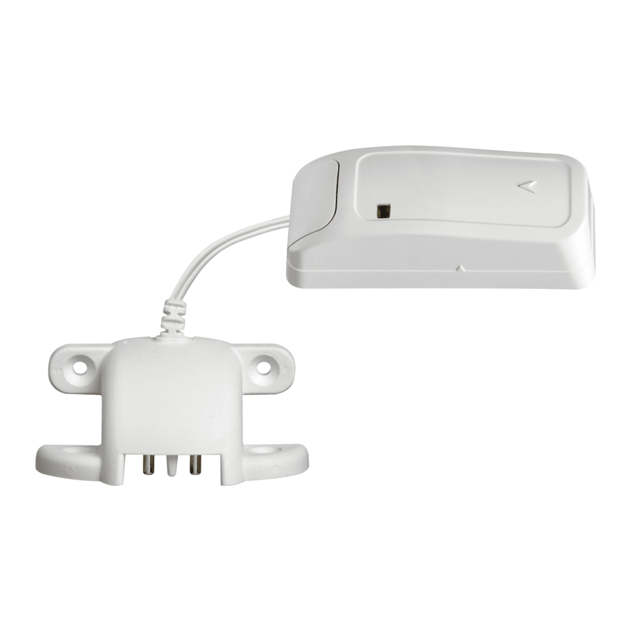
The PG9985/PG8985/PG4985 are fully supervised two-way, indoor PowerG flood detectors. The PG9985/PG8985/ PG4985 continuously monitor for unacceptable water levels. If water is detected (e.g., when both probes are in contact with the water), the PG9985/PG8985/PG4985 wirelessly communicates an alarm condition to the alarm system.
The tamper switch is activated when the cover is removed. In addition, the device sends a probe disconnection alert upon the detection of a probe terminal connection failure.
An LED lights whenever alarm or tamper events are reported. The LED does not light while a supervision message is being transmitted.
Operating power is obtained from a 3V Lithium battery. When the battery voltage is low, a "low battery" message is sent to the receiver.
After every flood detection, each flood detector should be cleaned and dried.
Device Setup

To be installed by service persons in non-hazardous locations only. Risk of explosion if battery is replaced by an incorrect type. Observe polarity when installing batteries. Dispose of used batteries according to the manufacturer's instructions and according to local rules and regulations.
Note: To ensure the continued operation of all wireless devices after performing a system default, a global upload of all wireless programming via DLS is recommended before defaulting the system. After completing the system default, download the wireless programming.
Legend
- Transmission LED
- Terminal block for sensor
- Enroll button
- Tamper switch
- Mounting holes
- Break-away tamper
Install the battery
- Insert a flat-edged screwdriver into the slot and push upward to remove cover.

- Remove the screw and separate the cover from the base.

- Observe polarity and install battery.

- Connect the sensor wire to the terminal block.


Note: When manually programming wireless devices, if a device has been powered up for more than 48 hours it cannot be enrolled into the system until the device has been tampered and restored. When programming the panel using the Quick Enroll procedure follow the steps detailed in Enroll the Device into the System.
Note: After restoring a low battery trouble the system may take up to 5 minutes to clear the trouble.
Enroll the Device into the System
To quick enroll
- On a keypad press [*] [8] [Installer Code] [804] [000].
- Press and hold the device enroll button until the LED lights steady and then release the enroll button while the LED is still lit. A confirmation message then appears on the keypad.
- Press [*] key to confirm ID.
- Enter [3 digit zone #].
- Enter [3 digit zone type].
- Enter [1 digit partition #] for all desired partitions and press [#]. If using an LCD keypad you can scroll to the desired partitions and press [*] to toggle the partition.
- On an LCD keypad enter the label by using word library.
To pre-enroll
- Remotely configure the unique ID number into the system. For more information see the HSM2HOST manual.
- When on-site, press the device enroll button.
Note: If the wireless device has been powered for more than 48 hours without being enrolled, tamper and restore the device to enroll it.
Perform a placement test
Before permanently mounting any wireless device, temporarily mount the device and perform a Placement test with the water sensor connected.
- Tamper the device.
- Restore the tamper. The device now enters Placement test mode for 15 minutes.
- The red LED blinks once to identify that a signal is being sent to the receiver and then blinks three times to identify the signal strength. The following table indicates the received signal strength.
| LED response | Signal Strength |
| Green LED blinks | STRONG |
| Orange LED blinks | GOOD |
| Red LED blinks | POOR |
| No blinks | No communication |

Only GOOD or STRONG signal strengths are acceptable. If you receive a POOR signal from the device, re-locate it and re-test until a GOOD or STRONG signal is received.
Note: For UL/ULC installations, only STRONG signal levels are acceptable. After installation verify the product functionality in conjunction with the compatible receivers HSM2HOST9, HS2LCDRF(P)9, HS2ICNRF(P)9 and PG9920.
Note: For detailed Placement instructions refer to the control panel Reference Guide.
Mount the Device
Notes: Avoid mounting the transmitter portion of the device behind a metal object such as a washing machine, refrigerator, or freezer. RF signals can be affected by metal objects. After every flood detection, each flood detector should be cleaned and dried. Otherwise, the unit may not operate as intended due to the nature of different liquids.
Note: Adhesive tape not to be used for EU Market.

- Install the flood sensor in the lowest point in the room or where water is expected to pool with at least 2 supplied screws. The flood sensor must be mounted so both probes of the device are touching water when an alarm condition is desired.
- Secure the flood sensor cable to the wall. The flood sensor should be installed only in a vertical position and facing downward.
- Attach the flood transmitter to the wall. The flood transmitter should be placed as high up as possible on the wall to improve communication and to prevent the flood detector itself from coming into contact with water in the event of flooding.
- Remove the PCB board.
- Mark and drill 2 holes in the mounting surface and fasten the base with 2 countersunk screws. If using the break-away tamper, secure with an additional screw.

- Reattach the PCB, and reattach the cover to the base.

Note: External wiring shall be routed and protected in a manner that prevents:
- excessive strain on wire and terminal connections
- loosening of terminal connections
- damage of conductor insulation
- developing any other type of hazard (e.g. tripping due to loose cables.)
Configuration
To enter the wireless configuration section enter [804][Zone Number].
Device Toggles
[001][04] Supervision - Default [Y]
Enables supervision of the device.
Specifications
Frequency Band: CE Listed PG4985: 433MHz; CE/EN listed PG8985: 868MHz; FCC/IC/UL/ULC listed PG9985: 912-919 MHz
Communication Protocol: PowerG
Alarm Input: External flood probe
Supervision: Signaling at 4-min. intervals
Battery type: 3 V Lithium CR-123 type battery, Panasonic or GP only.
Battery Life Expectancy: 8 years (not tested by UL/ULC)
Low Battery Threshold: 2.2 V
Battery Supervision: Automatic transmission of battery condition data as part of periodic status report and immediately upon low battery condition detection.
Temperature Range: -10°C to +55°C (UL/ULC only verified the range 0° to 49°C)
Humidity: up to max. 93%RH, non-condensing
Dimensions: (LxWxD)81 x 34 x 25 mm (3-3/16 x 1-1/4 x 1 in.)
Weight (including battery): 53g (1.9 oz)
Compatible Receivers
433MHz Band: HSM2HOST4; HS2LCDRF(P)4;HS2IC-NRF(P)4; PG4920
868MHz Band: HSM2HOST8; HS2LCDRF(P)8; HS2IC-NRF(P)8;PG8920
912-919MHz Band: HSM2HOST9; HS2LCDRF(P)9; HS2ICNRF(P)9; PG9920
Note: Only devices operating in band 912-919MHz are UL/ ULC listed.

VideosDSC NEO PG9985 Flood Sensor Programming Video
Documents / ResourcesDownload manual
Here you can download full pdf version of manual, it may contain additional safety instructions, warranty information, FCC rules, etc.
Download DSC PG9985, PG8985, PG4985 - PowerG Wireless Flood Detector Installation
Advertisement


Need help?
Do you have a question about the PowerG PG9985 and is the answer not in the manual?
Questions and answers