Table of Contents
Advertisement
Quick Links
INSTALLATION
MANUAL
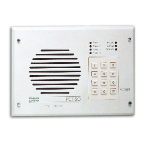
PC1150
This device complies with Parts 15 and 68 of the FCC rules. Operation is subject to the following two conditions: (1)
this device may not cause harmful interference, and (2) this device must accept any interference received, including
interference that may cause undesired operation.
MADE IN CANADA
REN = O.lB
Plug Type
FCC Reg. No.: FSCAN-73151-AL-E
firealarmresources.com
Advertisement
Table of Contents

Related Manuals for DSC PC1150


Summary of Contents for DSC PC1150
- Page 1 INSTALLATION MANUAL PC1150 This device complies with Parts 15 and 68 of the FCC rules. Operation is subject to the following two conditions: (1) this device may not cause harmful interference, and (2) this device must accept any interference received, including interference that may cause undesired operation.
- Page 2 NOTES FOR UL INSTALLATIONS This equipment is UL listed in accordance with UL 1023 (Household Burglar Alarm System Units). This equipment has not been investigated for compliance with UL 294, Access Control System Units. This equipment has the capability of being programmed for operational features that are not allowed for UL recognized installations.
-
Page 3: Table Of Contents
TABLE OF CONTENTS INTRODUCTION Features ............................... Specifications ............................INSTALLATION Mounting the Panel ..........................4 Assembling The Unit ..........................Mounting the Enclosure ........................Burglary Zone Wiring ........................... 5 Auxiliary Power Connection ......................... 5 PGM Terminal Connections ......................... 5 AC Power Wiring ..........................5 Battery Connection.. - Page 4 [01] 1st Phone Number ........................14 Reporting Code Sections [05] to [lo] ....................14 Zone Alarm Reporting Codes ....................14 Zone Restoral Reporting Codes ....................15 Closing (Arming) Reporting Codes / Partial Closing Reporting Code........15 Opening (Disarming) Reporting Codes /After Alarm Reporting Code ........16 Priority Alarms and Restorals ....................
-
Page 5: Features
INTRODUCTION SPECIFICATIONS FEATURES Keypad Programmable Four fully programmable zones The PC1 150 comes complete with a default program so that it is operational straight from the box with a End-of-Line (EOL) resistor supervised option minimum of programming. The control panel is Maximum zone zone resistance: 100 ohms completely programmable from the keypad. -
Page 6: Installation
INSTALLATION Mounting the Pane/ The keypad should be located close to the designated “Entry-Exit” door and be mounted at a height convenient for all users. Select a dry location close to an unswitched AC source and close to the telephone line connection. Remove the printed circuit board, the mounting hardware and the keypad from the cardboard packaging. -
Page 7: Burglary Zone Wiring
Burglary zone definition, (for example, Delay, Instant, 24-Hour, and so on) is programmed using the keypad. Refer to Programming Guide Section [ll]. For UL installations, zone inputs must be terminated with 1 kQ end-of-line resistors. NOTE: Burglary Zone Wiring Chart 1493 END OF LINE END OF LINE... -
Page 8: Keypad Functions Introduction
KEYPAD FUNCTIONS Introduction The PC1 150 keypad provides complete control of the PC1 150 control panel. The panel can be completely programmed from the keypad. The 4 zone lights provide alarm and status indication for the alarm circuits, and three function lights advise the user of system status. The built-in sounder lets the user hear correct key entries and other alert signals. -
Page 9: Arming Without Entry Delay
Arming Without Entry Delay To eliminate the Entry Delay, arm the system by entering [*][9][any Access Code]. An exit through a Delay Zone may be made as in normal arming. The system will arm as described in Auto-Bypass/ Home-Away arming whether an exit is made or not. -
Page 10: Display Alarm Memory
To display trouble conditions, enter [*][2]. Trouble conditions are represented with the following lights: Light Zone 1 Low Battery. lfthe batteryisdisconnected, itsvoltageis loworthe batteryfuseisopen, atrouble will be displayed and can be reported. Zone 2 AC Failure. On loss of AC power, the “System” light will come ON but the keypad buzzer will not sound. -
Page 11: User Programming Command
User Command Programming The [*][5] programming command allows the user to program Access Codes. The first Access Code is the Master Code and the installer may program the panel so that the user not able to change the Master Code; refer to Section [13]. -
Page 12: Setting The Clock
Setting the Clock The System Clock uses a 24-hour clock format. For example, 8:05 AM would be entered as 0805; 1:30 PM would be entered as 1330. If the system is without power (both AC and battery), it cannot continue to keep time. When the panel is powered up, the system clock must be reset. -
Page 13: Utility Output Command
Utility Output Command The Programmable Output (PGM terminal) can be programmed to be activated by a keypad command. This output can be used to operate devices such as door strikes or special lighting. Depending on the option chosen, the [ $][7] beentered. -
Page 14: Programming Guide
PROGRAMMING GUIDE With the panel disarmed, enter [*][8][lnstaller’s Code]. The default installer’s Code is 1212. The Installer’s Code should be changed after the system is installed; refer to Section [20] Installer’s Code. Note that the panel can only be programmed while it is disarmed. When the Installer’s Programming Command is entered, the “System”... -
Page 15: Binary Data Display
Binary Data Display Zone lights 1 through 4 are used to display the value of each digit of data in a binary format as shown here: HEX data entry Refer to HEX Data Programming Value Zone 1 Zone 2 Zone 3 Zone 4 0 Zone Light OFF HEX Data Programming... -
Page 16: Programmlng Sectlons
PROGRAMMING SECTIONS This is the first telephone number the Communicator will dial; refer to Section [25] Communicator Call Direction. Enter the telephone number the same way it would be dialled it on a touch-tone phone. Press [#] after the last digit to complete the telephone number programming. -
Page 17: [06] Zone Restoral Reporting Codes
Requires: Format Code [0], [l], [2], [3], [4] depending on receiver type in section [23]. Single line digit Alarm Reporting Code Section [05]. For example, enter [30] for single digit code 3 (0 = no pulses) TRANSMISSION SENT: 123 3 Requires: 4-digit account code in sections [02] or [04]. -
Page 18: Wi Opening (Disarming) Reporting Codes /After Alarm Reporting Code
Opening [Disamingj Reporting Codes /After Alarm Reporting Code Opening Reporting Codes are transmitted to indicate disarming of the system by Access Codes 1 through 6. When the system is disarmed by one of the Access Codes, the corresponding reporting code in this section is transmitted. - Page 19 Zone Definitions Digit 2 Digit 2 determines the zone type as described below: Standard Delay: Entry and Exit Delays are normally used for Entry/Exit doors. The Exit Delay starts when the system is armed; the zone may be opened and closed during the delay without causing an alarm. When the Exit Delay expires, opening the zone will start the Entry Delay.
-
Page 20: [12] 1St System Option Code
When Section [12] is entered, the 4 Zone Lights, “Ready” and “Armed” lights will indicate which options are enabled. If a light is ON, that option is enabled; if a light is OFF, that option is disabled. To enable or disable an option, press a number from [l] to [6]; [5] is used for the “Ready” light, and [6] is used for the “Armed”... -
Page 21: Ii41 3Rd System Option Code
Refer to Section [12] for programming information. LIGHT ON = Access code required for bypass OFF = Access code not required for bypass ON = Enable [*][4] downloading call feature OFF = Disable [*][4] call feature’ ON = Periodic downloading2 OFF = Periodic test transmission ON =... -
Page 22: Auxiliary Delay Zone Entry/Exit Times
“Slow” Zone Response Time (01 to 99 x IO ms) Location [5] determines the “slow” zone response time; this time is programmable from 10 ms to 990 ms. The default Slow Zone Response Time is 500 ms. NOTE: The fast zone response time is fixed at Test Transmission Cycle Time (01 to 99 days) Location [6] determines the frequency, in days, of the test transmission made through the communicator or by calling the downloading computer. -
Page 23: Communication Formats
This section determines the communication format to be used when transmitting information to the two telephone numbers programmed in Sections [Ol] and [03]. For each telephone number, enter one digit from the list below. Refer to “HEX Data Programming” for instructions on entering HEX numbers. The format for each phone number is determined by the type of receiver being called. -
Page 24: [24] Programmable Output Options / Pgm Terminal
Radionics Format For conventional Radionics 3/l format, the communications mode should be set on either Radionics rounds [B] or Radionics parity [Cl. The extended version of the Radionics format is normally used. Use the following guidelines to configure the PC1 150 for Radionics format: The customer account code must be only 3 digits with a zero making up the 4th digit. -
Page 25: Communicator Call Directions
Strobe Output (Latched Alarm Output) The PGM switches to ground on an alarm and remains low until the panel is disarmed. It can be used to indicate that an alarm has occurred before entering the premises. Failure to Communicate The PGM output switches to ground if the system fails to communicate after 8 attempts to each phone number that will be tried according to Section [25] Communicator Call Direction Options. -
Page 26: Reset To Factory Default
Software Reset Entering Section [30] will reset the control panel’s programming to the default settings. When Section [30] is entered, the keypad will beep several times and the “Trouble” light will come ON during the reset sequence. Hardware Reset If the Installer’s Code is forgotten and software reset cannot be performed, the panel may be reset to the default settings with the following method: Remove all power, AC and battery, from the panel... -
Page 27: 1321 5Th System Option Code
Installer’s Code. Entering Section [91] when in the installer’s programming mode will disable the Installer’s Lockout feature. Panels returned to DSC with the Installer’s Lockout feature enabled and no other apparent problems NOTE: will be subject to an additional service charge. -
Page 28: For The Record
PROGRAMMING WORKSHEETS In sections [Ol] to [lo], do not enter data into sections that are not used. NOTE: Page i4 Enter [0] for the digit 0 in the phone number. Enter [*4*] (HEX D) for additional dial tone detection between number digits, as in local PBX systems. Enter [#] to end the phone number entry Account Customer Code... -
Page 29: Programming Worksheets
Closing (Arming) Reporting Codes /Partial Closing Reporting Code Page f5 Access Code 1 Access Code Access Code Access Code Access Code 5 Access Code Partial Closing Code Opening (Disarming) Reporting Codes / After Alarm Reporting Code Page 16 The “after alarm” code is sent on disarming if an alarm occurred during the previous armed period. Access Code Priority Alarms &... - Page 30 Maintenance Alarms & Restorals Page Default For automatic test code reporting, time between reports (in days) must be specified in Section [17], and time of Low Battery Alarm day for the report must be entered in Section [ 191. AC Fail Alarm Fuse Failure Alarm Low Battery Restore AC Fail Restore...
- Page 31 2nd System Option Code Page 18 Default Zone Light ON Zone Light OFF Zone Light 1 Zone 4 N.O. without EOL Zone normal Zone Light 2 Master Code not changeable Master Code changeable Zone Light 3 Siren Squawk enabled. Siren Squawk disabled Zone Light 4 NOT USED NOT USED...
- Page 32 System Page 79 Times Default Entry Delay (seconds) Exit Delay (seconds) Siren Cut-off (minutes) AC fail transmission delay (minutes) Slow zone response time ( x 10 ms) Test transmission cycle or auto download cycle time (days) Valid entries are “01” to “99”; do not enter “00”. Zone Times Auxiliary Delay Page...
- Page 33 Formats Page 21 Default 1st Telephone Number l--J 2nd Telephone Number A format for both numbers must be programmed, even if the second telephone number is not used. Enter one HEX digit from [0] to [Fj for each phone number from the following list: Name Formats Handshake...
- Page 34 Communicator Call Direction Options Page 23 This section must be completely programmed; do not press [#] to exit until all entries are completed. Default Zone Alarms and Restorals [0] No transmissions for this group Access Code Openings and Closings Priority Alarms and Restorals Maintenance Alarms and Restorals Downloading Telephone Number Page 23...
- Page 35 Valid entries are “001” to “249” Installer’s Lockout Enable Page 25 Installer’s Lockout Disable Page 25 WARNING.’ Panels returned to DSC with the Installer’s Lockout enabled and no other apparent problems will be subject to an additional service charge! firealarmresources.com...
- Page 36 firealarmresources.com...
-
Page 37: Hookup Diagram
LIMITED WARRANTY Digital Security Controls Ltd. warrants that for a period of twelve months from the date of purchase, the product shall be free of defect in materials and workmanship under normal use and that in fulfilment of any breach of such warranty, Digital Security Controls Ltd. - Page 38 FCC COMPLIANCE STATEMENT This equipment generates and uses radio frequency energy, and if not installed and used properly, in strict accordance with the manufacturer’s instructions, may cause interference to radio and television reception. It has been type tested and found to comply with the limits for a class “B”...
Need help?
Do you have a question about the PC1150 and is the answer not in the manual?
Questions and answers