Table of Contents
Advertisement
Advertisement
Table of Contents

Summary of Contents for Turnigy 9XR
- Page 1 Turnigy 9XR User Manual...
-
Page 2: Table Of Contents
Table of Contents Disclaimer………………………………………………………………………… Introduction……………………………………………………………………… How it works………………………………………………………………… Nomenclature …………………………………………………………………… Edit buttons ……………………………………………………………………… Navigation ………………………………………………………………………… Editing and Saving ……………………………………………………………… On Startup– Quick Model Select ………………………………………………… Transmitter Layout ……………………………………………………………… Main Screen……………………………………………………………………… General View……………………………………………………………………… Statistics Screens Statistics Screens…………………………………………… General Settings………………………………………………………………… Radio Setup (1/5) ……………………………………………………………… Trainer (2/5) ……………………………………………………………………... -
Page 3: Disclaimer
Disclaimer THIS FIRMWARE IS PROVIDED ON AN "AS-IS" BASIS WITHOUT WARRANTY OF ANY KIND AND ANY EXPRESS OR IMPLIED WARRANTIES, INCLUDING, BUT NOT LIMITED TO, THE IMPLIED WARRANTIES OF MERCHANTABILITY AND FITNESS FOR A PARTICULAR PURPOSE ARE DISCLAIMED. IN NO EVENT SHALL THE DEVELOPER AND/OR AUTHOR BE LIABLE FOR ANY DIRECT, INDIRECT, INCIDENTAL, SPECIAL, EXEMPLARY, OR CONSEQUENTIAL DAMAGES (INCLUDING, BUT NOT LIMITED TO: PERSONAL AND/OR PROPERTY DAMAGE) HOWEVER CAUSED AND ON ANY THEORY OF LIABILITY,... -
Page 4: How It Works
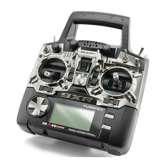
Introduction The 9XR is a computerized radio from Turnigy. The transmitter is outfitted with a 128x64 pixel monochrome LCD, two x 2 axis gimbals, three variable potentiometers (pots), six 2-position switches, one 3-position switch and some funky Digital trims. How it works... -
Page 5: Nomenclature
What the heck was that? The system receives 4 types of inputs: 1. Main Sticks 2. Potentiometers 3. Trims 4. Switches The analog inputs (sticks and pots) go through a calibration phase. The sticks can also go through Expo and Dr filters before going to the mixer. The mixer does it all. -
Page 6: Edit Buttons
Edit buttons There are 6 edit buttons on the Tx. In this manual they are noted with square brackets ([MENU]). Some functions need the button to be pressed and held for a second or so. The are noted as “long”presses like so: [MENU LONG] The “!”... -
Page 7: Editing And Saving
Editing and Saving As a rule once a value is changed it is saved. You can turn off your Tx and turn it back on and the values will be saved. The values are saved internally in the MCU's eeprom. However there is a slight delay sometimes so it's probably a good idea to wait a couple of seconds before turning off. -
Page 8: Transmitter Layout
Transmitter Layout... -
Page 9: Main Screen
Main Screen General view The main view is split into top and bottom. The top contains the following: • The current model's name. (GOOFI in this case and yes, it's a real airplane) • The battery voltage. • Trim increment information. •... - Page 10 Statistics Screens STAT 08:02 TOT STAT2 TME 08:02 00:00 TSW tmr 1Lat max 5 us STK 00:00 00:00 ST% tmr 1Lat min 5 us tmr 1 Jitter 0 us tmain 6,31 ms Stack 0123 b [MENU] to refresh From the main screen pressing [UP LONG]/[DOWN LONG] will enter the statistics screen. The first shows some available timers and traces the throttle stick as well.
-
Page 11: General Settings
General Settings From the main screen pressing [LEFT LONG] will enter the general settings menus. Here you can set up settings that will be the same regardless of chosen model. The menus are as follows: • Radio Setup • Trainer settings and PPM In Calibration •... -
Page 12: Radio Setup
Radio Setup (1/5) RADIO SETUP Owner Name ME OF COURSE Beeper Quiet Contrast BAT Warning 9.0v Inactivity Alarm 0m Mode ↔☼ ↕☼ ☼↕ ☼↔ 2 RUD THR ELE AIL Use this screen to set up general functions for the Tx: 1. - Page 13 it's a nice feature. The reverse will also reverse the throttle warning on startup and some other throttle related functions. 8. Minute beep: Beeps every full minute while the timer is running. 9. Countdown beep: Beeps at 30, 20, 10, 3, 2 and 1 seconds before the timer ends. 10.
-
Page 14: Trainer
Trainer (2/5) TRAINER mode % src sw RUD := 100 ch4 TRN THR := 100 ch3 TRN ELE := 100 ch2 TRN AIL := 100 ch1 TRN Multiplier 1.0 This menu allows the PPMin (trainer) inputs to be configured. It enables the RAW PPM inputs to be selected to replace the sticks for training purposes. -
Page 15: Diagnostics
Diagnostics (3/5) DIAG THR 0 RUD 0 Left 0 ELE 0 Right 0 ID1 1 Trim- + 0 ID2 0 ↔☼ 0 0 Down 0 AIL 0 ↕☼ 0 0 Exit 0 GEA 0 ☼↕ 0 0 This menu will help you visualize the current state of the trims, keys and physical switches. Each Key/Switch/Trim is represented. -
Page 16: Calibration
Calibration (5/5) CALIBRATION START CALIBRATION [MENU] TO START This screen allows you to calibrate the analog channels (A1..A7). The calibration method goes like this: 1. Press [MENU] → (SetMid) 2. Set Sticks to center. (Including throttle and pots) 3. Press [MENU] → (SetSpan) 4. -
Page 17: Model Setup
Model Setup From the main screen pressing [LEFT RIGHT] will enter the model select/settings menus. Here you can set up settings that model specific. The menus are as follows: 1. Model Select 2. Model Setup 3. Heli Setup 4. Expo/Dr 5. -
Page 18: Model Select
Model Select (1/11) MODELSEL free 1560 1/11 *01 GOOFI 02 YAK 55 In this screen you can see, select, copy and move models between different memory “slots”. I quote the word “slots” because memory management is dynamic. The available memory is displayed at the top of the screen. -
Page 19: Model Setup
Model Setup (2/10) SETUP 01 2/11 Name GOOFI Timer 15:00 Trigger Ths TriggerB Timer Count Down T-Trim Lots of options here: 1. Name: Unsurprisingly here you edit the model's name. To edit: scroll down until the name is highlighted and press [MENU]. Once your press [MENU] only one letter will remain highlighted. - Page 20 9. T-Trim: Throttle trim. This is a nifty feature for power fliers. When activated a couple of things happen. First off the center detent for the throttle trim is removed. Also the throttle's trim will now only affect the “low” side. That means you can use the trim for setting idle while full throttle remains unchanged.
- Page 21 This deletes the current model. You need to press [MENU LONG] for that to happen though. WARNING! Deleting a model causes the memory to jump to the previous model memory in the list. Do not delete a model memory while you have a model "listening". Always shut down your receiver before deleting a model.
-
Page 22: Heli Setup
Heli Setup (3/11) HELI SETUP 3/11 Swash Type Collective ---- Swash Ring ELE Direction NOR AIL Direction NOR COL Direction NOR This screen is specifically designed to help you set up a CCPM heli. 1. Swash Type: This defines what kind of Swash plate you have on your heli: i. -
Page 23: Expo/Dr
Expo/Dr (4/11) EXPO/DR 4/11 exp % sw1 sw2 RUD 0 100 - --- --- H THR 50 100 - --- --- H ELE 0 100 - --- --- H AIL 0 100 - --- --- H This screen allows you to enter and edit Expo and D/R values for the main controls (RUD/ELE/THR/AIL). -
Page 24: Mixer
axis. With the switch in the up position, it will be at low rate, as indicated by the "L" at the end of the line. In the mid position, it will be mid rate, and at the down position, it will be at high rate. You can also include throttle if you'd like, to have different expo curves for each of the flight modes. -
Page 25: Edit Mix
Edit Mix EDIT MIX CH1 Source Weight Offset FlMdoetrim Trim Curves Switch In this screen you edit individual mixes. Here are the available options for each mix: 1. Source: This is the input for the mix. It can be the following: i. - Page 26 it’s use would be using it as a LAND function, cut the throttle, flip the switch, and use the elevator trim to set a good glide angle. 5. Trim: When this is “ON” the trim value (if exists) will be carried on through the mix. When“OFF” it is ignored.
-
Page 27: Limits
Limits (6/11) LIMITS 6/11 CH1 -5.9 -100→ 100 CH2 0.7 -100→ 100 CH3 0.0 -95 ← 40 CH4 -14.4 -100→ 100 CH5 45.9 -100→ 100 CH6 0.0 -100→ 100 This is probably the second most important menu. The limits operate on the output channels (as you can see from the flow chart in the introduction). In the LIMITS menu you can set the center point (subtrim), limits (both left and right) Each channel here corresponds to a channel in your receiver. -
Page 28: Reverse
Reverse (7/11) REVERSE 7/11 CH1 NOR The reverse operate on the output channels and reverse the channel's output (REV – reverse). 1. REV: Reverse. This function reverses the output of the channel. Press [MENU] to trigger. -
Page 29: Curves
CV1 -75 -40 0 45 75 Surprisingly in this menu you set your custom curves. Curves are nifty things that can tell your servo how to move when you move your stick. In 9XR there are eight 5-point curves and eight 9- point curves. -
Page 30: Custom Switches
Custom Switches (9/11) CUSTOM SWITCHES 9/11 SW1 v<ofs THR SW2 ---- ---- SW3 ---- ---- SW4 ---- ---- SW5 ---- ---- SW6 ---- ---- Custom switches are not really switches at all but rather a set of logical conditions that can be used as switches. -
Page 31: Safety Switches 10/11
Safety Switches (10/11) SAFETY SWITCHES 10/11 CH1 S --- 0 CH2 S --- 0 CH3 S --- 0 CH4 S --- 0 CH5 S --- 0 CH6 S --- 0 Safety switches allow you to select a switch and have it write a value for a channel that will overwrite any other value. -
Page 32: Templates
Templates (11/11) TEMPLATES 11/11 01 Simple 6-ch 02 T-Cut 03 V-Tail 04 Elevon\Delta 05 Heli Setup Channel Order RETA The templates are there to help you get started. When entering the screen you'll see a list of available templates. To choose a template, scroll down to it and press [MEU LONG]. This will add the template to the existing mixes. -
Page 33: Examples
Examples Programming a throttle cut Though you can use a template for this it's instructional to do it via the mixer. Start off with the default 6 mixes. Scroll down until CH1 is underlined, like this: MIXER 5/11 CH1 100% THR CH2 100% AIL CH3 100% ELE CH4 100% RUD... - Page 34 Keep on scrolling down until you reach Multpx. Change the value to “Replace” EDIT MIX CH1 Weight -100 Offset Trim Curves Switch Warning Multpx Replace Now press [EXIT] You should see the following screen: MIXER 5/11 CH1 100% THR R-100% FULL THR CH2 100% AIL CH3 100% ELE CH4 100% RUD...
-
Page 35: Build And Program Instructions
This Section is for Advanced Users/Programmers Build and Program Instructions You might want to play with the code and modify the 9XR to suit your own needs. It's really easy if you know a little C. First, to program the MCU, download the full programing instructions: Flashing the 9x by Jon Lowe. -
Page 36: Make Targets
• AVRDUDE_PROGRAMMER: Set avr programmer name - default: usbasp (to list all available: avrdude -c ?) • TARGET: Set target name - default: tgy-9XR • OPT: Set optimization level - default: s • FORMAT: Set format (can be srec, ihex, binary) - default: ihex... -
Page 37: Software/Firmware Acknoledgements
9XR firmware. We look forward to seeing the 9XR embraced for what it is, that is the peoples radio, and look forward to watching the software develop alongside new hardware solutions as they become available.
Need help?
Do you have a question about the 9XR and is the answer not in the manual?
Questions and answers