
Subscribe to Our Youtube Channel
Related Manuals for Westinghouse IQ DATA


Summary of Contents for Westinghouse IQ DATA
- Page 1 TO 172838 IQ DATA LINE METERING SYSTEM USER'S MANUAL @Westinghouse Effective April, 1991 ELECTRICAL COMPONENTS DIVISION...
- Page 2 If further information is desired by purchaser regarding his particular installation, operation or maintenance of his equipment, the local Westinghouse Electric Corporation representative should be contacted.
-
Page 3: Table Of Contents
..... . . IQ Data ......4 Optional Power Module 2 . -
Page 4: Iq Data
7. If you think a problem exists, check the voltage and current readings with hand-held meters. If they are correct, the unit 4. Connect CT inputs to the CT terminals of the IQ Data. Be should be operating correctly. If an LED is not functioning, extremely careful to connect the inputs correctly and to line return the device to the factory for repairs. -
Page 5: Introduction
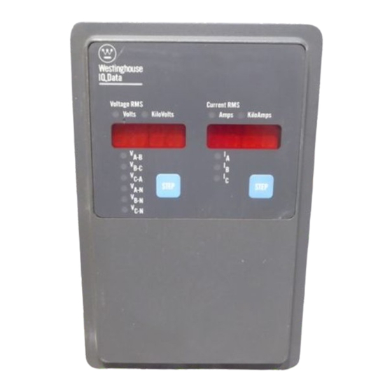
The program directing the monitoring function is permanently contained, door-mounted device designed to both monitor and stored in the IQ Data, and so there is no need to reload display electrical parameters. (See Figure 1.1) programs after an AC power loss. -
Page 6: Use Of Manual
If the cause of malfunction is traced to an IQ Data, the unit specific IQ Data application. should be replaced with a spare. The malfunctioning unit should then be returned to Westing house for factory repairs. -
Page 7: Hardware Description
2.0 General- The purpose of this Section is to familiarize The description here is divided into the following: the reader with the IQ Data hardware, its nomenclature, and Operator Panel (Par. 2 .1.1) • to list the specifications of the unit. -
Page 8: Rear Access Area
IQ DATA 2.1.1 Operator Panel- The Operator Panel, which is nor When using the IQ Data without the 3-phase Power Module, mally accessible from the outside of the panel or door, pro study Figure 2.1A and note the following items: vides a means to: 1. -
Page 10: Specifications
Terminals. (See Figures 4 . 4 B, 4 . 4 D and 4 . 4 F.) 5. DIP switches, located on the right side of the chassis, tailor each IQ Data to a specific application . These DI P 2.2 Specifications-... -
Page 11: Operator Panel
TO 172838 IQ DATA Section 3 OPERATOR PANEL 3.0 Introduction- item is shown in the Display Window. This Section describes the operation of the 10 Data. It is divided into the following 3 Sections: For example, while the LED is illuminated, the STEP pushbutton is pressed once. -
Page 12: Units Leos
TO 172838 IQ DATA Table 3.A MET ERED VAL UES Display Selection Description Format XXXX V A-B Volts RMS Phases A-to-8 xx.xx XXXX V8_ c Volts RMS Phases 8-to-C xx.xx XXXX Vc-A Volts RMS Phases C-to-A xx.xx XXXX VA-N Volts RMS (1) Phase A-to-neutral XX. -
Page 13: Installation And Startup
Do not use a tap on the face since this preparation and mounting of the IQ Data. will remove excessive plastic from the holes, resulting in less threaded material to secure the IQ Data to its mounting panel. 4.1.1 Cutout, C learances- Since the IQ Data is typically mounted on a cabinet's door, it is necessary to prepare a 5.12... -
Page 14: Optional Power Module
Figure 4.2 Optional Power Module Place the IQ Data through the cutout in the panel. Be sure the Operator Panel faces outward. Use 0.5 in. (1. 2 em) long screws (included with the IQ Data) to mount the unit on a inside single-thickness panel. - Page 15 AC Line Connection Terminals on the chassis, when line voltage is 600 volts or less. 3. The wires connecting to the IQ Data must not be larger than AWG No. 14. Larger wires will not connect properly with the various terminal blocks.
-
Page 16: Wiring
TD 172838 IQ DATA PHASE WIRE (UP TO VOLTS) 2 CT's WITH IQ DATA DIRECT VOLTAGE C ONNECTION & EXTERNAL CURRENT TRANSFORMERS LOAD LINE LOAD • .. E- 1 20 2 40 VW:. CONTROL POWER " >ll Gtrll (SEE LABEL FOR... - Page 17 TO 172838 IQ DATA PHASE WIRE (UP TO VOLTS) DIRECT VOLTAGE CONNECTION & EXTERNAL CURRENT TRANSFORMERS LOAD LIN� XI E- • Xl f2 AND 6 NOTE: 1>101[: UH(S LINES 2, 4, SHOULD �AIN ED AT THE POT[ tll "L AT !HE SAM£ POIENI"l SAWE >S THE GND TERII...
- Page 18 120 OR 240 VIC CONTROL POWER " "' � � Glfl WlEL (SEE 120/240 Jl)ljP[RS) IQ DATA STAND ALONE APPLICATION Figure 4.4E - Wiring Diagram PHASE WIRE (ABOVE VOLTS) EXTERNAL POTENTIAL TRANSFORMERS & CURRENT TRANSFORMERS LINE 120 OR 240 VIC CONlRDl POWER Gl() �...
-
Page 19: Dip Switch Settings
Verify all DIP switches are set according to the lnstalla· T his is the last step if installing an IQ Data without a three tion Record Sheet. phase Power Module. Verify that all wiring is correct, as shown on the wiring plan drawings. - Page 20 · . · · · · · · · Table 4.A IQ DATA INSTALLATION REC ORD SHEET Setting Slide ON/OFF Description Switch S witch Combinations T he ratio of the external current transformers. Refer to Table 5. A, page 20...
-
Page 21: Display Current
- This Section contains various considerations 5.0 General Table 5.A to be kept in mind when applying the IQ Data to a specific CT RATIO SET T INGS application. It is designed primarily for the systems or appli cation engineer responsible for making up the wiring plan SW1 Switch Settings ( 1l drawings. -
Page 22: Wire/4 Wire Line
ON position for a 3-wire wiring configuration • allow the IQ Data to calculate and display the original, un When the OFF position is selected for the 3-wire configuration, reduced line voltage even though the level at the AC Line Con... -
Page 23: Theory Of Operation
6.0 General ory device. (The actual signals from the AC line are "con of how the IQ Data functions internally. Its purpose is to give ditioned" by various circuits grouped together here and the user only an overview theory of operation. -
Page 24: Maintenance
One or both display windows do not display values and/or • IQ Data. Failure to do so can result in serious or even fatal the lA AMPS RMS LED or V A B VOLTS RMS LED are not personal injury and/or equipment damage. -
Page 25: Operational Troubleshooting
10 DATA TD 172838 Table 7.8 Probable Cause(s) Symptom luti All Operator Panel indicators are off. Control power is deficient. Locate control power deficiency. • • Unit is malfunctioning. Replace unit. (See Paragraph 7.2) • • Before attempting to troubleshoot the 10 Data and the a wire connection. - Page 26 � part of a constant effort to serve your needs, Westinghouse is interested in any information you can supply about your application or use of the 10 DAT A. If you would like to share this information, please check the box below.
- Page 27 · - - - - - - - - - - - - - - - - - - - - - - - - - - - - - - - - - - - - - - - - - - - - - - - - - - - - - - - - - - - - - - - - - - - - - - - - - - - - - - - - - - - - - - - - - - - - - - - - - - - PLACE STAMP HERE Westinghouse Electric Corporation Parkway Center 1 5220...
Need help?
Do you have a question about the IQ DATA and is the answer not in the manual?
Questions and answers