Table of Contents
Advertisement
Scan or Click the above QR Code or go to
https://www.automationdirect.com/VID-FL-0003
for a short quick start video.
Operating instructions
Magnetic-inductive flow meter
Scan or Click the above QR Code or go to
https://www.automationdirect.com/VID-FL-0006
for an explanation of Magnetic Inductive Flow Meters
by Automationdirect.com
FMM50 1002
FMM75 1002
FMM100 1002
Advertisement
Table of Contents

Related Manuals for Prosense FMM50-1002


Summary of Contents for Prosense FMM50-1002
-
Page 1: Operating Instructions
Operating instructions Magnetic-inductive flow meter FMM50 1002 FMM75 1002 FMM100 1002 Scan or Click the above QR Code or go to Scan or Click the above QR Code or go to https://www.automationdirect.com/VID-FL-0003 https://www.automationdirect.com/VID-FL-0006 for a short quick start video. for an explanation of Magnetic Inductive Flow Meters by Automationdirect.com... -
Page 2: Table Of Contents
Contents 1 Preliminary note ....................4 1.1 Symbols used ....................4 1.2 Warning signs used ..................4 2 Safety instructions ....................4 3 Functions and features ..................5 4 Function .......................6 4.1 Measuring principle for flow rate monitoring ..........6 4.2 Processing of the measured signals ..............6 4.3 Flow rate measurement .................7 4.4 Temperature monitoring .................7 4.5 Flow rate or temperature monitoring / analog function ........8... - Page 3 10.4 User settings (optional) ................17 10.4.1 Setting of the standard unit of measurement for temperature ..17 10.4.2 Setting of the standard unit of measurement for flow rate ....17 10.4.3 Configuration of the standard display ..........18 10.4.4 Setting of measured value damping ..........18 10.4.5 Setting of the error behaviour of the outputs ........18 10.5 Service functions ..................18 10.5.1 Reading the min/max values for the flow rate ........18...
-
Page 4: Preliminary Note
1 Preliminary note 1.1 Symbols used ► Instruction > Reaction, result […] Designation of keys, buttons or indications → Cross-reference Important note Non-compliance can result in malfunction or interference. Information Supplementary note. 1.2 Warning signs used CAUTION Warning of personal injury. Injuries may result . -
Page 5: Functions And Features
• For medium temperatures above 122 °F some parts of the housing can heat up to over 149 °F. Moreover, during installation or in case of a fault (e.g. housing damage) media under high pressure or hot media can leak from the system. To avoid personal injury, take the following measures: ►... -
Page 6: Function
4 Function 4.1 Measuring principle for flow rate monitoring The magnetic-inductive measuring principle means that a magnetic field is gener- ated in the measuring pipe via current-carrying coils. When a conductive medium flows through the measuring pipe, the ions therein are diverted perpendicularly to the magnetic field. -
Page 7: Flow Rate Measurement
4.3 Flow rate measurement An analog signal which is proportional to the flow rate (4...20 mA) is provided on output 2 in case of medium flow in the measuring pipe. (On the analog functions → 4.5) In addition to the flow rate, the unit also detects the flow direction. An arrow on the unit indicates the positive flow direction. -
Page 8: Flow Rate Or Temperature Monitoring / Analog Function
4.5 Flow rate or temperature monitoring / analog function Current output [mA] [°C] Characteristics of the analog output according to the standard IEC 60947-5-7 1: Output current 2: Flow rate 3: Temperature 4: Display range 5: Measuring range 6: Range between analog start point and analog end point 7: The unit is in the error state (FOU = OFF) 8: The process value transmitted in an analog way is therefore below the display range 9: Curve of the analog signal at factory setting... -
Page 9: Installation
5 Installation ► Avoid deposits, accumulated gas and air in the pipe system. 5.1 Recommended installation locations Example of an optimized installation: ► Install the unit so that the measuring pipe is completely filled. ► Arrange for inlet and outlet pipe lengths. Disturbances caused by bends, valves, reductions, etc. -
Page 10: Not Recommended Installation Position
The unit can be installed irrespective of the orientation if the following is ensured: - No air bubbles can form in the pipe system. - The pipes are always completely filled. 5.2 Not recommended installation position ► Avoid the following installation positions: Directly in front of a falling pipe. -
Page 11: Grounding
5.3 Grounding If installed in an ungrounded pipe system (e.g. plastic pipes), the unit must be grounded (functional earth). Ground brackets for the M12 connector are available as accessories → www.automationdirect.com). 6 Electrical connection The unit must be connected by a qualified electrician. The national and international regulations for the installation of electrical equipment must be adhered to. -
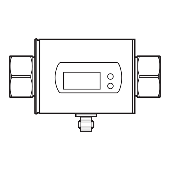
Page 12: Operating And Display Elements
7 Operating and display elements 1 to 8: Indicator LEDs - LED 1 = current flow rate in liters/minute. - LED 2 = current flow rate in cubic meters/hour. - LED 3 = current flow rate in gallons per minute (gpm). - LED 4 = current flow rate in gallons per hour (gph). -
Page 13: Menu
8 Menu 8.1 Menu structure = [Mode/Enter] = [Set] In the Run mode, different display units are accessible (depending on the setting of the parameters [SELd], [Uni.F] and [Uni.T], → 10.4). -
Page 14: Explanation Of The Menu
8.2 Explanation of the menu ASP1 Analog start value for temperature. AEP1 Analog end value for temperature. ASP2 Analog start value for flow rate. AEP2 Analog end value for flow rate. Extended functions / opening of menu level 2. HI.F Maximum value memory for flow rate. LO.F Minimum value memory for flow rate. -
Page 15: Set-Up
9 Set-up After power on and completion of the power-on delay time (approx. 5 seconds) the unit is in the normal operating mode. It carries out its measurement and evaluation functions and generates output signals according to the set parameters. ►... -
Page 16: Parameter Setting In General
10.1 Parameter setting in general Select parameter ► Press [Mode/Enter] until the requested parameter is displayed. Changing the parameter value ► Press [Set] and keep it pressed. > Current setting value of the parame- ter flashes for 5 s. > After 5 s: The setting value is chan- ged: incremental by pressing briefly or scrolling by holding pressed. -
Page 17: Locking / Unlocking
10.1.2 Locking / unlocking The unit can be locked electronically to prevent unintentional settings. On delivery: not locked. Locking ► Make sure that the unit is in the normal operating mode. ► Press [Mode/Enter] + [Set] for 10 s. > [Loc] is displayed. During operation: >... -
Page 18: Configuration Of The Standard Display
10.4.3 Configuration of the standard display ► Select [SELd] and determine the standard process category. - [FLOW] = display shows the current flow rate value in the standard unit of measurement. - [TEMP] = display indicates the current medium temperature in the standard unit of measurement. -
Page 19: Reading The Min/Max Values For The Temperature
10.5.2 Reading the min./max. values for temperature ► Select [HI.T] or [LO.T] and press [Set] briefly. [HI.T] = maximum value, [LO.T] = minimum value. Speicher löschen: ► Select [HI.T] or [LO.T]. ► Press [Set] and keep it pressed until [----] is displayed. ►... -
Page 20: Reading The Parameter Value
r r u l f t r r u l f t r r u l f t r r u l f t e r r C ° e r r F ° 11.2 Reading the parameter value Select parameter ►... -
Page 21: Technical Data
12 Technical data Technical data and scale drawing at www.automationdirect.com. 13 Factory setting Factory setting User setting FMM50- FMM75- FMM100- 1002 1002 1002 ASP1 -20.0 -20.0 -20.0 AEP1 80.0 80.0 80.0 ASP2 AEP2 25.0 50.0 100.0 FOU1 FOU2 Uni.F Lmin Lmin Lmin Uni.T...
Need help?
Do you have a question about the FMM50-1002 and is the answer not in the manual?
Questions and answers