Table of Contents
Advertisement
Quick Links
Advertisement
Table of Contents

Subscribe to Our Youtube Channel
Related Manuals for Prosense DPM2-P Series


Summary of Contents for Prosense DPM2-P Series
- Page 1 DPM2-P S enSe erieS igital anel eter requency achoMeter ounter oDeS Models: DPM2-P-HL DPM2-P-2R-HL Scan or click the QR code for a series of Configuration and Programming videos for the ProSense DMP Series Panel Meters...
-
Page 2: Table Of Contents
User Manual - DPM2-P Series Digital Panel Meters In this Chapter... General Information ......................4 Package Contents ......................4 Recycling Instructions ....................4 General Safety Considerations ..................4 Symbols Identification ....................4 Maintenance ........................5 Technical Support ......................5 Agency Certifications ....................5 Description ........................5 Features ........................6 Dimensions and Mounting ....................6 Installation........................7... - Page 3 User Manual - DPM2-P Series Digital Panel Meters Relay Setpoints Configuration ..................17 Counter Mode (‘Cont’) ....................18 Tachometer Mode (‘tACH’ and ‘rAtE’) ................18 Function modes description ..................19 HI/LO mode activation ....................19 Time delay (Tachometer mode ‘tACH’ and ‘rAtE’ only) ..........19 Asymmetrical hysteresis (Tachometer mode ‘tACH’ and ‘rAtE’ only) ......19 1, 2, 3 and 4 control modes (for counter mode ‘Cont’...
-
Page 4: General Information
User Manual - DPM2-P Series Digital Panel Meters General Information Package Contents • DPM2-P Series digital panel meter • Quick start guide • Mounting panel accessories (a sealing gasket and 2 fixing clips) • Wiring accessories (plug-in terminal block connectors and 2 key tools for wire insertion) •... -
Page 5: Maintenance
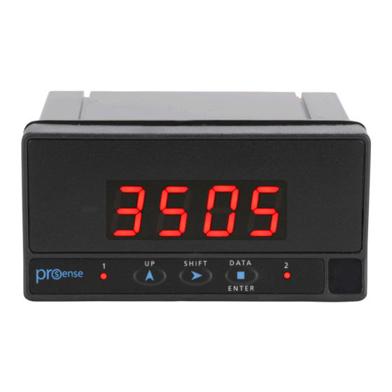
Agency Certifications Description The ProSense DPM2-P series offers a simple, low cost digital display for counter, tachometer, rate, and frequency applications. The DPM2-P has a 4-digit 14mm character height red LED display, accepts input from AC voltage, magnetic sensors, NPN/PNP sensors, NAMUR sensors, TTL/24V encoders, or switched contacts, and provides selectable sensor excitation voltages. -
Page 6: Features
User Manual - DPM2-P Series Digital Panel Meters Features • 96 x 48mm 1/8 DIN • 4 digit (0 to 9999) red LED display • Selectable decimal point • Counter/Tachometer/Rate(Frequency) modes - AC voltage - Magnetic sensor - NAMUR sensor... -
Page 7: Installation
User Manual - DPM2-P Series Digital Panel Meters Dimensions mm [in] Installation Installation Dimensions 96 x 48 x 83.1mm (1/8 DIN) To install the meter, prepare a 92mm x 45mm panel 92 x 45mm Panel Cutout (Max. panel thickness 10mm) - Page 8 User Manual - DPM2-P Series Digital Panel Meters AC Supply DC Supply Relay 1 Relay 2 Signal Input 1 Line 1 VDC - IN (Common) 2 Neutral 2 VDC + IN + EXC 8 VDC Polarity insensitive for + EXC 24 VDC...
-
Page 9: Wiring Examples
User Manual - DPM2-P Series Digital Panel Meters Wiring Examples Wiring for Magnetic Sensor and Switched Contact Input Signal DPM2-P MAGNETIC SENSOR / SWITCHED CONTACT -IN (COMMON) Wiring for NAMUR Sensor Input Signal DPM2-P NAMUR SENSOR +EXC +EXC 8V DC... -
Page 10: Relay Output Wiring
User Manual - DPM2-P Series Digital Panel Meters Remote Counter RESET Function Wiring O.C. OUTPUT SWITCHED CONTACT DPM2-P DPM2-P RESET RESET -IN (COMMON) -IN (COMMON) Note: In both cases, main counter RESET is activated through 1 and 5 terminals when contact is closed and it remains active until the contact is again opened . -
Page 11: Display And Keypad
User Manual - DPM2-P Series Digital Panel Meters Display and Keypad Pro mode is when configuration menu is entered to program the indicator. RUN is the normal mode in which display shows the reading according to configuration and input signal value. -
Page 12: Configuration
User Manual - DPM2-P Series Digital Panel Meters Configuration When power is applied to the meter, a display test begins automatically to check the function of LED’s and digits. Once this test is finished, the display shows the internal software version and then the unit goes to RUN mode. -
Page 13: Input Configuration
User Manual - DPM2-P Series Digital Panel Meters Input Configuration The first menu corresponds to input configuration which consists of seven options, one for each input signal type: (-1-), (-2-), ..(-7-) Signal Type: AC voltage input (10-600 VAC) Magnetic sensor... -
Page 14: Display Configuration
User Manual - DPM2-P Series Digital Panel Meters Display Configuration The second menu corresponds to display configuration consisting of submenus according to previously programmed input type. #1 Counter Mode #2 Tachometer Mode #3 Rate Mode dECP Counter Mode (#1) If selected operating mode is counter (Cont), the displayed routine after pressing dECP ENTER will be as shown here. -
Page 15: Rpm Tachometer Mode (#2)
User Manual - DPM2-P Series Digital Panel Meters RPM Tachometer Mode (#2) If selected operating mode is rpm tachometer (tACH), the displayed routine after pressing ENTER will be as shown here. Configure the number of pulses per revolution provided by the sensor connected to the input. -
Page 16: Example Of Configuration
User Manual - DPM2-P Series Digital Panel Meters Example of Configuration: It is desired to measure the speed in m/s of a conveyor belt which is driven by a shaft turning at 300 rpm that is 20 cm in diameter and provides 4 pulses per revolution. -
Page 17: Relay Setpoints Configuration
User Manual - DPM2-P Series Digital Panel Meters TIME LIMIT “tLiM” Time limit, programmable from 1 to 99 seconds (10s by default), is the waiting time limit until at least 1 pulse is received at the input before considering it to be ‘zero’. If no pulse is detected before programmed time is elapsed, the display goes to zero. -
Page 18: Counter Mode ('Cont')
User Manual - DPM2-P Series Digital Panel Meters Counter Mode (‘Cont’) CONTROL MODES (FOR SETPOINT 2 ONLY): ModE MODE 1: INDEPENDENT MODE 2: STOP - 1 - - 4 - MODE 3: RESET MODE 4: CLEAR ACTIVATING MODE: Hi: High level relay activation. -
Page 19: Function Modes Description
User Manual - DPM2-P Series Digital Panel Meters Function modes description Alarms are independent, they become active when display value reaches Setpoint level programmed by the user (Setpoints can not be referenced to the totalizer). For a complete configuration it is necessary to define the function mode, as well. -
Page 20: And 4 Control Modes (For Counter Mode 'Cont' And Setpoint 2 Only)
User Manual - DPM2-P Series Digital Panel Meters 1, 2, 3 and 4 control modes (for counter mode ‘Cont’ and Setpoint 2 only) Outputs are respectively shown overlapped in the following diagrams as pulse output latch output OVER MODE 1: INDEPENDIENT... -
Page 21: Pulse Output "Puls" (Counter Mode Only 'Cont')
User Manual - DPM2-P Series Digital Panel Meters Pulse output “PuLS” (Counter mode only ‘Cont’) Relay activates when its Setpoint is reached by display and deactivates after a period of time. This activation time is a parameter which can be programmed between 0.1s and 9.9s. -
Page 22: Max/Min Tachometer Mode ('Tach' And 'Rate')
User Manual - DPM2-P Series Digital Panel Meters MAX/MIN Tachometer Mode (‘tACH’ and ‘rAtE’) This device detects and stores in memory maximum and minimum values reached by the input signal. These values remain in memory when the power supply is removed. When pressing the SHIFT key repeatedly, MAX/MIN function shows saved maximum and minimum values in display since last RESET function activation. -
Page 23: Return To Default Configuration
User Manual - DPM2-P Series Digital Panel Meters Return to default configuration To access this menu from RUN mode, press ENTER key and while display shows “Pro” press ENTER again for at least 3 seconds. Display shows “00” and the code ‘74’ must be entered through SHIFT and UP keys. -
Page 24: Configuration Lock-Out
User Manual - DPM2-P Series Digital Panel Meters CONFIGURATION LOCK-OUT Lock-out menu In order to prevent accidental or undesirable modifications of meter parameters, a selective or total configuration lock-out is available. By default the unit is delivered unlocked, giving access to all programming levels. Once in this menu, the first option will be to choose between lock-out level setting (“LiSt”) or security access code changing (“CHAn”). - Page 25 User Manual - DPM2-P Series Digital Panel Meters RESET function activated through UP key can be blocked, as well (only when operating as counter ‘Cont’). NOTE: Totalizer RESET function lock-out is not available and it will always remain active. SHIFT key lock-out for MAX/MIN function is configurable in the same way as previous configurations (only when operating as tachometer ‘tACH’...
-
Page 26: Technical Specifications
User Manual - DPM2-P Series Digital Panel Meters Technical Specifications Technical Specifications 7.5 kHz (counter mode) Maximum Frequency 25kHz (tachometer rpm or rate modes) Signal Input Minimum Frequency (tachometer rpm or rate modes) 0.01 Hz AC voltage Input Range 10 to 600 VAC... - Page 27 User Manual - DPM2-P Series Digital Panel Meters Technical Specifications Continued Range 0 to 9999 Type 4 digit, 14mm (0.55”) Totalizer (counter mode) 0 to 999999 Decimal point Configurable LEDs Relay 1, Relay 2 Display refresh rate (tachometer rpm or rate modes) 0.1 s to 9.9 s (configurable)
-
Page 28: Instrumentation Configuration Notes
User Manual - DPM2-P Series Digital Panel Meters Instrumentation Configuration Notes INPUT: TYPE: CONT TACH RATE MODE: DISPLAY: MULT. FACTOR: OFFSET: PPR: DISP. VARIATION: INPUT FREQUENCY: DISPLAY: TMAX.: TLIM.: SETPOINTS: SET1: ACT. MODE: DLY / PULSE TIME: HYS / LATCH:...
Need help?
Do you have a question about the DPM2-P Series and is the answer not in the manual?
Questions and answers