Table of Contents
Advertisement
Quick Links
Download this manual
See also:
User Manual
Advertisement
Table of Contents

Related Manuals for Rigol M300


Summary of Contents for Rigol M300
- Page 1 RIGOL Quick Guide M300 Data Acquisition/Switch System Jul. 2013 RIGOL Technologies, Inc.
-
Page 3: Guaranty And Declaration
Notices RIGOL products are protected by patent law in and outside of P.R.C. RIGOL reserves the right to modify or change parts of or all the specifications and pricing policies at company’s sole decision. Information in this publication replaces all previously corresponding material. -
Page 4: Safety Requirement
If you suspect damage occurs to the instrument, have it inspected by qualified service personnel before further operations. Any maintenance, adjustment or replacement especially to circuits or accessories must be performed by RIGOL authorized personnel. Keep Well Ventilation. Inadequate ventilation may cause increasing of temperature or damages to the device. -
Page 5: Safety Terms And Symbols
CAUTION indicates a potential damage to the instrument or other property might occur. Symbols on the Product. These symbols may appear on the product: Hazardous Safety Protective Chassis Test Warning Earth Ground Ground Voltage Terminal M300 Quick Guide... -
Page 6: General Care And Cleaning
Please contact your local authorities for disposal or recycling information. M300 Quick Guide... -
Page 7: Table Of Contents
Measurement Connections ............... 23 Using External Terminal Blocks ............23 To Connect the Signal to be Measured ..........26 To Configure Scan List ................27 Configuration Copy .................. 29 Channel Monitor ..................30 Remote Control ..................31 Troubleshooting ..................33 M300 Quick Guide... -
Page 9: Document Overview
RIGOL would not be responsible for free maintenance/rework or replacement of the unit. 2. Inspect the instrument In case of any damage, or defect, or failure, notify your RIGOL sales representative. 3. Check the accessories Please check the accessories according to the packing lists. If the accessories are incomplete or damaged, please contact your RIGOL sales representative. -
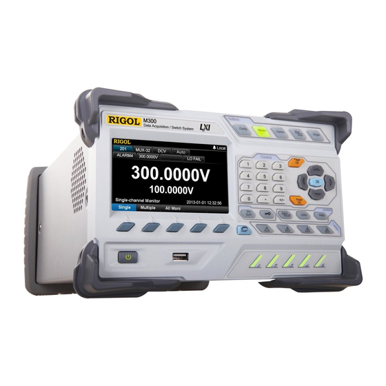
Page 10: Appearance And Dimensions
RIGOL Appearance and Dimensions Figure 1 Front View (Unit: mm) Figure 2 Side View (Unit: mm) M300 Quick Guide... -
Page 11: Front Panel
Support single-channel, multi-channel and all-channel monitor functions. In single-channel monitor function, you can switch the channel monitored at any time. In multi-channel monitor function, you can monitor up to 7 channels in the scan list. M300 Quick Guide... - Page 12 Direction keys and confirmation key. 4. System Keys If a USB storage device is currently connected to the instrument, press this key to store the current content on the screen in USB storage device in *.bmp format. M300 Quick Guide...
- Page 13 Press this key to turn on or off the instrument. 7. USB Host Via this interface, M300 can be as a host device and connected with an USB storage device to store or recall instrument status, measurement configuration, measurement data, etc.
- Page 14 10. Module Indicators Correspond to the 5 module slots at the rear panel respectively. The corresponding module indicator goes on when the module is inserted into the slot at the rear panel. M300 Quick Guide...
-
Page 15: Rear Panel
Figure 4 Rear Panel 1. Slots M300 provides 5 slots for 5 modules and only one DMM module is permitted for one mainframe. The 5 slots from left to right in the figure above correspond to the 5 module indicators at the front panel respectively. When a module is inserted in the slot, the corresponding module indicator at the front panel goes on. - Page 16 Please use the specified fuse to avoid electric shock and fire. 6. Voltage Selector M300 supports two kinds of AC voltages (115 V and 230 V). Please select the proper voltage scale according to the AC power used. 7. RS-232/Alarms/Ext Trig Mix Interface (Male) This interface is 25-pin male interface.
- Page 17 PC and you can control the instrument remotely via the 9. Power Socket M300 can accept two kinds of AC power supplies. Use the power cord provided in the accessories to connect the AC power supply to the instrument via this socket.
- Page 18 RIGOL 10. Power Fuse The specification of the fuse of M300 is AC 250V T3.15 A. If a new fuse is required, please refer to the following steps. 1) Turn off the instrument and remove the power cord. Insert the small straight screw driver into the slot at the power socket and prize out the fuse seat.
-
Page 19: Power On And Inspection
1. Connect the power Adjust the power voltage selector at the rear panel according to the power supply voltage. M300 supports two types of AC power: if your supply voltage is in the range of 115*(1-10%) V and115*(1+10%) V, please select 115 and if it is in the range of 230*(1-10%) V and 230*(1+10%) V, please select 230. -
Page 20: User Interface
For more detailed information, please refer to the User’s Guide. 3. Menu Bar Display the menus of the current function corresponding to the menu softkeys below respectively. Pressing the softkey can activate the corresponding menu. M300 Quick Guide... -
Page 21: Plug-In Module Overview
RIGOL Plug-in Module Overview M300 provides 10 kinds of modules including the DMM module, 32-channel multiplexer, 64-channel multiplexer, multi-function module, etc. This section introduces the functions and characteristics of each module. Outside View drawing of the module Golden Circuit board Edge: each on the... -
Page 22: Insert The Module Into The Mainframe
Figure 7 Insert the Module into the Mainframe Note: All the modules of M300 do not support hot-plugging. Please turn the mainframe off before inserting the modules into the mainframe. M300 Quick Guide... -
Page 23: Module Overview
This module can be connected with MC3065 (DMM Module, if MC3065 is currently inserted). For the specifications of this module, please refer to the User’s Guide or Data Sheet of this product. M300 Quick Guide... - Page 24 100 kHz TOT) with 1 Vpp sensitivity 4 analog output terminals, ±12 V calibrated voltage For the specifications of this module, please refer to the User’s Guide or Data Sheet of this product. M300 Quick Guide...
- Page 25 Dual 4-channel RF multiplexer. MC3724 consists of two independent 4-to-1 multiplexers and can switch high frequency signal or pulse signal. For the specifications of this module, please refer to the User’s Guide or Data Sheet of this product. M300 Quick Guide...
-
Page 26: To Use The Built-In Help System
RIGOL To Use the Built-in Help System The built-in help system of M300 provides the help information about any front panel key and menu. To acquire the help information of any front panel key or menu, press Help (the backlight goes on and “Help” is displayed in the status bar in the user interface) and then press the desired key. -
Page 27: Menu Quick Navigation
RIGOL Menu Quick Navigation This section provides the structures of the main menus for M300 to guide users to quickly get familiar with the operations. For more detailed information, please refer to the User’s Guide. Config M300 Quick Guide... -
Page 28: Monitor
RIGOL Monitor M300 Quick Guide... -
Page 29: Control
Edit the output value of the channel selected (2) TOT channel: MC3534 Read the count of the channel selected; Start or stop counting (3) DAC channel: edit the output value of the channel selected (4) Module reset M300 Quick Guide... -
Page 30: View Switch Key
RIGOL View Switch Key Press repeatedly to view the scan history information, channel status table, measurement curve and channel information. Alarm Channel Setting Keys M300 Quick Guide... -
Page 31: Basic Operations
Measurement Connections Using External Terminal Blocks M300 provides 6 kinds of terminal blocks to easily connect the signal to be measured to the module. The models of the terminal blocks and its corresponding modules are listed in the table below. This section introduces how to use the external block. - Page 32 Connect the terminal block to the module via interface 1 (the interface definition is in Figure 6) on the module and screw down the two screw rods onto the nuts on the module. M300 Quick Guide...
- Page 33 RIGOL Close the upper cover of the terminal block. Insert the module with the terminal block into the slot of the mainframe. M300 Quick Guide...
-
Page 34: To Connect The Signal To Be Measured
Resistance to be measured Source Resistance to be measured Thermocouple Thermocouple Sense under test CH17 Note: Only available for all the channels of MC3132 and MC3232 as well as the channel 1 to channel 20 of MC3324. M300 Quick Guide... -
Page 35: To Configure Scan List
Select Range and use the left/right direction keys to select the desired range (for example, 2V). Note: The parameters needed to be set in this step depend on the selected function. (2) Step 2: Scaling Configuration Select Scaling and use the left/right direction keys to enable the scaling M300 Quick Guide... - Page 36 Press New and configure other channels to the scan list according to the step 3. 5. Save the scan list After the scan list configuration is completed, press Save to save the configured scan list in internal or external memory M300 Quick Guide...
-
Page 37: Configuration Copy
RIGOL Configuration Copy M300 provides configuration copy function (including module copy, channel copy and extended copy) which can configure multi channels with same configuration to the scan list easily and quickly. Press Config Edit Copy to enter the copying interface. -
Page 38: Channel Monitor
Channel Monitor The channel monitor function of M300 allows users to monitor a single channel, multiple channels or all of the channels in the scan list. The instrument monitors the channel and takes readings from the channel monitored continuously even during a scan. -
Page 39: Remote Control
2. To control the instrument via USB (1) Connect the devices Connect the USB Device interface of M300 to the USB Host interface of your computer using the USB cable. (2) Install the USB driver This instrument is a USB-TMC device. - Page 40 USB interface information of the instrument will also be displayed as shown in the figure below. (5) Communication test Right click the resource name “M300 (USB0::0x1AB1::0x0C80::M3001111333::INSTR)” to select “SCPI Panel Control” to turn on the remote command control panel (as shown in the figure below) through which you can send commands and read data.
-
Page 41: Troubleshooting
This section lists some questions and failures which might occur when using this instrument. Please solve them according to the following method. If the problem remains, please contact RIGOL and provide the device information of your instrument (Utility Info). - Page 42 9. If the information of the module is displayed correctly, the module indicator is possibly damaged, please contact RIGOL to consult maintenance information. 9. Unable to view the information of the module or unable to use the...
- Page 43 If DHCP is disabled and Auto IP is enabled, please ensure the IP addresses of M300 and computer is in the same network segment. If Manual IP is enabled, please ensure the IP addresses of M300 and computer is in the same network segment.
Need help?
Do you have a question about the M300 and is the answer not in the manual?
Questions and answers