Sign In
Upload
Manuals
Brands
Unipower Manuals
Power Supply
XR08.48
Unipower XR08.48 Manuals
Manuals and User Guides for Unipower XR08.48. We have
2
Unipower XR08.48 manuals available for free PDF download: Instruction Manual
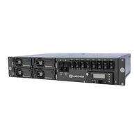
Unipower XR08.48 Instruction Manual (49 pages)
Power Supply System Aspiro 2U Front Access
Brand:
Unipower
| Category:
Power Supply
| Size: 2 MB
Table of Contents
Table of Contents
3
Chapter 1 About this Manual
6
Objectives
6
Audience
6
Document Key
6
Feedback & Support
7
Disclaimer
7
Chapter 2 Aspiro System Description
8
Overview
8
Figure 2-1 Power System Overview
8
System Parameters
9
System Components
11
System Controller
11
DC Distribution Unit
11
Rectifier Module
12
Figure 2-2 Xpge12.48 and XR04.48/XR08.48
12
Chapter 3 System Safety
13
Safety Warnings and Guidelines
13
System Markings
13
Safety Recommendations
13
Installation Warning
14
Restricted Access Area Warnings
14
System Enclosure
14
Operating Temperature Warnings
14
Electrical Safety Warnings
15
Grounding
16
Batteries
16
Lead Acid Batteries
16
In Case of an Accident
17
Caution
17
Storage and Transportation
17
Disposal
17
Handling Electrostatic Sensitive Devices
17
Traceability
17
Breakers
18
Hot Surfaces
18
Chapter 4 Installation Guide
19
Unpacking
19
Tools
19
Rack Mounting
19
Figure 4-1 System Mounting
20
Figure 4-2 Slide Bracket Fixing
20
Cable Entry
21
Figure 4-3 System Bracket Fixing
21
Figure 4-4 System with Cover Removed
21
AC Input Connection
22
Figure 4-5 Grounding Connection
22
DC Load Connection
23
Figure 4-6 AC Input Terminal Block (1-Phase)
23
Figure 4-7 AC Connection Options
23
Battery Connection
24
Figure 4-8 DC Load Connection
24
Alarm and Signal Connections
25
Figure 4-9 Battery Connection
25
Figure 4-10 Alarm Connections
25
Symmetry Connection
26
Figure 4-11 2-Block Symmetry Measurement (for Illustration Only)
26
Temperature Sensor Connection
27
Figure 4-12 4-Block Symmetry Measurement (for Illustration Only)
27
Figure 4-13 Temperature Sensor Connection
27
Rectifier Installation
28
Figure 4-14 Rectifier Installation
28
Connection of External PDU to DC Parallel Kit (Option)
29
Reinstalling Top Cover
29
Figure 4-15 External PDU Connection
29
Figure 4-16 DC Parallel Principle
29
Chapter 5 Commissioning
30
Commissioning Overview
30
Tools and Test Equipment
30
Tools List
30
Test Equipment
30
Preparation
30
Commissioning Procedure
31
Test of Output Voltage
32
Float Charge (U1)
32
Adjustment of Float Charge, U1
32
Boost Charging (U2) (if Applicable)
32
Table 5-1 Float/Boost Charge Voltages
32
Battery Supervision
33
Battery Test
33
Commissioning Record
34
Table 5-2 Commissioning Record
34
Chapter 6 Maintenance & Troubleshooting
35
Maintenance
35
Checking Terminal Connection
35
Troubleshooting
35
Table 6-1 Connection Torque Setting Check
35
Chapter 7 Replacing Modules
40
Controller Replacement
40
Figure 7-1 Unlocking the Controller
40
Figure 7-2 Removing the Controller
40
Rectifier Replacement
41
XR04.48 / XR08.48 Replacement
41
Xpge12.48 Replacement
41
Figure 7-3 Replacing an XR04.48 or XR08.48 Rectifier
41
Battery and Load Breakers Replacement
42
Figure 7-4 Replacing an Xpge12.48 Rectifier
42
Figure 7-5 Removing the Front Panel
42
Figure 7-6 Removing the Top Cover
43
Figure 7-7 Pulling out a Faulty Breaker
43
Surge Protection Device Replacement
44
Other Requirements
44
Appendix A - Drawings
45
Block Diagram
47
Advertisement
Unipower XR08.48 Instruction Manual (44 pages)
Brand:
Unipower
| Category:
Power Supply
| Size: 1 MB
Table of Contents
Table of Contents
3
Chapter 1 About this Manual
6
Objectives
6
Audience
6
Document Key
6
Feedback & Support
7
Disclaimer
7
Chapter 2 Aspiro System Description
8
Overview
8
System Configurations
8
Figure 2-1 Power System Overview
8
System Parameters
9
System Components
11
System Controller
11
DC Distribution
11
Rectifier Module
12
Figure 2-2 Xpge12.48 and XR04.48/XR08.48
12
Chapter 3 System Safety
13
Safety Warnings and Guidelines
13
System Markings
13
Safety Recommendations
13
Installation Warning
14
Restricted Access Area Warnings
14
Electrical and Fire Enclosure
14
System Enclosure
14
Operating Temperature Warnings
14
Electrical Safety Warnings
14
Grounding
15
Batteries
16
Lead Acid Batteries
16
In Case of an Accident
16
Caution
17
Storage and Transportation
17
Disposal
17
Handling Electrostatic Sensitive Devices
17
Traceability
17
Breakers
17
Circuit Breaker Limitations
17
Chapter 4 Installation Guide
19
Introduction
19
Unpacking
19
Tools
19
Rack Mounting
19
Figure 4-1 Dimensional Drawing (Front and Top View)
20
Figure 4-2 System Mounting (19" Mount)
20
Rear Connections
21
DC Earth Connection (FRAME GROUND)
21
Figure 4-3 Rear Connections
21
Figure 4-4 DC Earth Connections
21
Mains Connection
22
Figure 4-5 Mains Connection (Viewed from Rear)
22
Table 4-1 Recommended Mains Circuit Protection
22
Alarm and Signal Connections
23
Figure 4-6 Mains Connection Detail
23
Figure 4-7 Signal Pin Designations
24
DC Load Connections
25
Figure 4-8 Signal Connection Detail
25
Figure 4-9 Load and Battery Connections (Rear View)
25
Battery Connections
26
Figure 4-10 Signal Connection Detail
26
Table 4-2 Cable Sizes
26
Symmetry Connection
27
Figure 4-11 2-Block Symmetry Measurement (for Illustration Only)
27
Figure 4-12 4-Block Symmetry Measurement (for Illustration Only)
27
Table 4-3 Cable Sizes
27
Temperature Sensor Connection
28
Figure 4-13 Temperature Sensor Connection
28
Chapter 5 Commissioning
29
Commissioning Overview
29
Tools and Test Equipment
29
Tools List
29
Test Equipment
29
Preparation
29
Commissioning Procedure
30
Test of Output Voltage
31
Float Charge (U1)
31
Adjustment of Float Charge, U1
31
Boost Charging (U2) (if Applicable)
31
Table 5-1 Float/Boost Charge Voltages
31
Battery Supervision
32
Battery Test
32
Commissioning Record
33
Table 5-2 Commissioning Record
33
Chapter 6 Maintenance & Troubleshooting
34
Maintenance
34
Troubleshooting
34
Chapter 7 Replacing Modules
38
Controller Replacement
38
Figure 7-1 Unlocking the Controller
38
Figure 7-2 Removing the Controller
38
Rectifier Replacement
39
XR04.48 / XR08.48 Replacement
39
Xpge12.48 Replacement
39
Figure 7-3 Replacing an XR04.48 or XR08.48 Rectifier
39
Breaker Replacement
40
Figure 7-3 Replacing an Xpge12.48 Rectifier
40
Figure 7-5 Top Cover Removal
40
Figure 7-6 Breaker Removal - a
41
Figure 7-7 Breaker Removal - B
41
Appendix A - Block Diagram
42
Appendix B - CSA Certificate Extract
43
Appendix C - Revision History
44
Advertisement
Related Products
Unipower XR04.48
Unipower Gravitas X100
Unipower XPGe12.48
Unipower X100 SERIES
Unipower X75 Series
Unipower ARE Series
Unipower ARE130AC12F
Unipower ARE130AC16F
Unipower ARE130AC25F
Unipower ARE130AC35F
Unipower Categories
Power Supply
Power distribution unit
Inverter
Battery Charger
Measuring Instruments
More Unipower Manuals
Login
Sign In
OR
Sign in with Facebook
Sign in with Google
Upload manual
Upload from disk
Upload from URL