Advertisement
Quick Links
Basler Electric
Phone 618 654-2341
Route 143 Box 269
Highland IL 62249 USA
INTRODUCTION
The
AVC63-12
and
AVC125-10
Regulators are contained in encapsulated plastic
cases. The regulators control the amount of dc
excitation to the exciter field of conventional
brushless synchronous generators.
Regulation is provided by sensing the generator
output voltage, converting it to a dc signal and
comparing the signal to a reference voltage signal.
An error signal is developed and used to control
the dc field power in order to maintain a constant
generator output.
The regulator includes frequency compensation
with selectable slope, inverse-time overexcitation
shutdown, solid-state build-up circuitry, single-
phase or three-phase voltage sensing, single-
phase or three-phase shunt, or permanent magnet
generator power input, parallel droop compen-
sation, and an accessory input. The accessory in-
put provides compatibility with accessories such as
a var/power factor controllers or excitation limiters.
ELECTRICAL SPECIFICATIONS
Power Output
AVC63-12: 12 Adc @ 63 Vdc maximum con-
tinuous. 24 Adc @ 125 Vdc forcing for 10
seconds. Minimum field resistance: 5.25
AVC125-10: 10 Adc @ 125 Vdc maximum
continuous. 20 Adc @ 250 Vdc forcing for 10
seconds. Minimum field resistance, 12.5
Input Power Requirements
Single- or three-phase, 50 to 400 Hz
AVC63-12: 90 to 153 Vac, 1092 VA
maximum continuous burden.
AVC125-10: 180 to 264 Vac, 1750 VA maxi-
mum continuous burden.
Sensing Input Voltage and Frequency
Single- or three-phase. Sensing voltage option
A: 90 to 139 Vac, sensing voltage option B:
180 to 264 Vac. Sensing frequency option 1:
50 or 60 Hz nominal, sensing frequency option
2: 400 Hz nominal. (For more style/option
information see Table 4.)
Input Sensing Burden
Less than 1 VA.
Auxiliary Input
± 3Vdc for use with SCP250 VAR/PF Controller
or EL200 Min/Max Excitation Limiter.
External Voltage Adjust Rheostat
10k ohm, 2 W potentiometer.
Regulation Accuracy
±0.5% of voltage set point, average responding.
Voltage Drift
±0.5% voltage variation for a 40°C (104°F)
change.
Response Time
< 4 milliseconds.
Frequency Compensation
One or two V/Hz jumper selectable with knee
Publication:
9 3372 00 991
INSTRUCTIONS
AUTOMATIC VOLTAGE REGULATOR
AVC63-12
adjustable from 45 to 65 Hz for 50/60 Hz units
and 300 to 430 Hz for 400 Hz units. Reference
Voltage
Figure 1 for 60 Hz and Figure 2 for 400Hz
sensing models. (Figures are not in numerical
order to conserve space in this document.)
EMI Suppression
Internal filter. (See CE Conformity below.)
Voltage Build-Up
Provisions for automatic voltage build-up from
generator residual voltages as low as: 6 Vac for
AVC63-12 and 12 Vac for AVC125-10 units.
Overexcitation Shutdown
Overexcitation shutdown protection reduces the
output voltage to zero for the following voltages
in the times shown. Other voltages and times
are based on inverse time characteristic curves
as shown in Figures 3 and 4.
AVC63-12:
125 Vdc ±10% in approximately 10 seconds.
210 Vdc ±10% in approximately 1 second or
less.
AVC125-10:
250 Vdc ±10% in approximately 10 seconds.
370 Vdc ±10% in approximately 1 second or
less.
$
Droop/Line Drop Compensation
.
<10 VA adjustable from 0 - 10% of rated input
current, 0.8 power factor. (LDC compensates
$
.
for voltage drop due to line reactance and
reactive components of the load current only.)
Agency Approvals
UL Recognized per Standard 508, UL File No.
E97035.
CSA Certified per Standard CAN/CSA-C22.2
No. 14-95, CSA File No. LR 23131
CE Conformity. Conforms to:
Radiated Emissions . . . . . . . . EN50081-2.
Radiated Immunity:
Electric field . . . . . EN61000-4-3 (10 V/m).
Conducted . . . . EN61000-4-6 (10 VRMS).
Conducted Emissions . . . . . . EN50081-2.
(EN55011, Class A).
ESD Immunity . . . . . . . . . . . . . EN50082-2
(4 KV contact, 8 KV air).
EFT Immunity . . . . . . . . . . . . . EN50082-2
(2 KV coupling clamp).
Magnetic Immunity . . . . . . . . . EN50082-2
(30ARMS, 50 Hz).
Safety: . . . . . . . . . . . . . . . . . . EN61010-1.
Operating and Storage Temperature
-40°C to +70°C (-40°F to +158°F).
Relative Humidity
95% non-condensing
Shock
Withstands 20 g in each of three mutually
perpendicular planes.
Vibration
Withstands the following accelerations at the
Rev
A
FOR
AVC125-10
AND
Power Systems Group
Fax 618 654-2351
http://www.basler.com
info@basler.com
stated frequency: 4.5 g; 18 to 2000 Hz.
Weight
Approximately 1.1 kg (2.5 lbs.)
INSTALLATION
The regulator may be mounted in any position.
Refer to the outline drawing (Figure 5). The
regulator may be mounted directly on the
generator set using UNF 1/4-20 or equivalent
hardware.
Select the proper hardware to
withstand any expected shipping/transportation
and operating conditions.
CONNECTIONS
Before connecting the AVC63-12 or the
AVC125-10 into your system, review the
terminal descriptions provided in Table 1, the
internal adjustments provided in Table 2, and
the diagrams shown in Figures 6 through 8.
Table 1. Terminal Descriptions
Term.
Term.
Number
Description
Upper Term. Strip
CH GND
Chassis ground connection
Auxiliary Input from var
2
Power Factor Controller
Auxiliary Input from var
3
Power Factor Controller
Connect to 7 to use internal
4
voltage adjust, no
connection for external
voltage adjust
5
1 Amp Current Transformer
5a
5 Amp Current Transformer
6
Current Transformer
Common
Common connection for
6a
selectable features
Connect Remote Adjust
7
from 7 to 6a, connect to 4
for internal voltage adjust
Connect to 6a to select
8
1v/Hz underfrequency slope
Connect to 6a to select 3
9
phase sensing
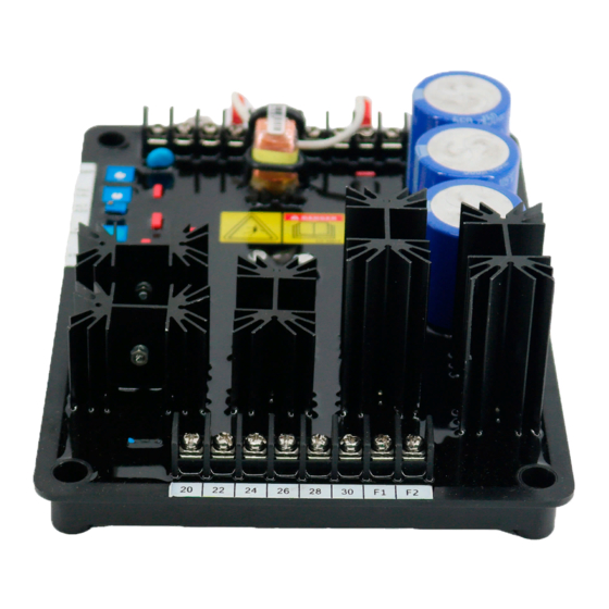
Lower Term. Strip
20
Phase C sensing input
22
Phase A sensing input
24
Phase B sensing input
26
3-phase power input
28
1-phase or 3-phase power
input
30
1-phase or 3-phase power
input
F1
Field +
First Printing
06/2001
Revised
08/2001
Copyright
2001
Advertisement

Related Manuals for Basler AVC63-12


Summary of Contents for Basler AVC63-12
- Page 1 250 Vdc ±10% in approximately 10 seconds. Power Output Auxiliary Input from var 370 Vdc ±10% in approximately 1 second or AVC63-12: 12 Adc @ 63 Vdc maximum con- Power Factor Controller less. tinuous. 24 Adc @ 125 Vdc forcing for 10...
- Page 2 (3) Rotate the front panel STB control CCW This option allows the AVC63-12 and the voltage is less than 6 Vac for the AVC63-12 or until the system just begins to oscillate and AVC125-10 to regulate the var and power factor...
- Page 3 OPERATIONAL TEST 1. Perform the preliminary set-up. This test is designed to test all eight models of Input the AVC63-12 and AVC125-10. See Table 4 for 2. Start prime mover and bring up to rated Sensing appropriate testing voltages and frequencies.
- Page 4 2 3 4 5 5a 6 6a 7 8 90 110 130 150 170 190 210 230 DC Output Voltage Chassis AVC63-12 Ground Figure 3. AVC63-12 Overexcitation Shutdown Characteristics AVC125-10 Sensing Power Output 20 22 24 26 28 30 F1 F2 Shutdown Region...