Table of Contents
Advertisement
Advertisement
Chapters
Table of Contents

Related Manuals for Omron SYSMAC C20P


Summary of Contents for Omron SYSMAC C20P
- Page 1 Cat. No. W167-E1-4A SYSMAC Programmable Controllers C20P/C28P/C40P/C60P...
- Page 2 P-type Programmable Controllers Installation Guide Revised July 1994 C20P C60P C20P C60P...
- Page 4 OMRON. No patent liability is assumed with respect to the use of the information contained herein. Moreover, because OMRON is constantly striving to improve its high–quality products, the information contained in this manual is subject to change without notice.
-
Page 6: Table Of Contents
TABLE OF CONTENTS SECTION 1 Introduction ........Nomenclature . - Page 7 About this Manual: This manual has been prepared to provide the information necessary to install, set up, and maintain your C-series P-type Programmable Controller, a low-cost, compact, versatile industrial control sys- tem providing up to 148 I/O points. For information regarding system programming and operation, refer to the Operation Manual.
- Page 8 SECTION 1 Introduction Nomenclature ............1-1-1 CPUs .
-
Page 9: Nomenclature
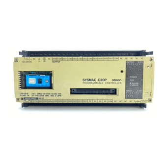
Nomenclature Section 1-1 Nomenclature This section gives the names and functions of the various components of P-type PCs and the basic Units with which they can be combined in a System. 1-1-1 CPUs In the diagram below, the C28P is shown as a representative model. Refer to Appendix A Standard Models for your model’s exact specifications. -
Page 10: Expansion I/O Units
Nomenclature Section 1-1 ROM Socket and DIP Beneath the cover are the DIP switch and the socket where an EPROM chip Switch may be installed. For details, see 2-8-1 Setting the CPU DIP Switch and 2-8-2 EPROM Installation. Only DIP switch pins 1 and 2 are on when the CPU is delivered. - Page 11 Nomenclature Section 1-1 Indicators The following diagram shows the functions of the various indicators, taking the C20P as an example. OUTPUT 5 CH OUTPUT: Shows whether the output is ON or OFF. POWER: Stays lit while power is turned ON to the POWER I/O Unit.
-
Page 12: Analog Timer Unit
Nomenclature Section 1-1 Vertical Mounting All Units except the C16P and C4K can be positioned vertically. C20P-CN411 Set to Right in Left out I/O Unit 1-1-3 Analog Timer Unit Internal variable resistors These variable resistors are used to set the timers Min. -
Page 13: I/O Link Units
Nomenclature Section 1-1 External Variable Resistor The contactor employs solderless terminals and must be wired as shown be- low, using AWG 22 to 28 lead wires. Analog Timer Unit connector External variable resistor (20 kW) 1-1-4 I/O Link Units The I/O Link Unit must be used as a Remote I/O Slave, and must be used with a Remote I/O Master. -
Page 14: System Configuration
System Configuration Section 1-2 System Configuration Depending on your control requirements, you can combine various Units for a total number of I/O points ranging anywhere from 20 to 148. A P-type PC consists of a CPU Unit plus one or more of the following Units: Expansion I/O Units, Analog Timer Units, Analog I/O Units, or an I/O Link Unit. - Page 15 System Configuration Section 1-2 The symbols used in the table represent the following: C20P/C28P C20P or C28P CPU Unit Input Output C40P/C60P C40P or C60P CPU or Input Output Input Output Expansion I/O Unit C4K/C16P C4K or C16P Expansion I/O Unit Input Output C20P/C28P/TU/AN/LU...
- Page 16 System Configuration Section 1-2 IR 00 IR 05 IR 01 IR 06 IR 02 IR 07 IR 03 IR 08 IR 04 IR 09 C4K/C16P C4K/C16P C4K/C16P C4K/C16P C20P/C28P Input Output Input Output Input Output Input Output Input Output C20P/C28P/TU/AN/LU Input Output C4K/C16P...
- Page 17 System Configuration Section 1-2 IR 00 IR 05 IR 01 IR 06 IR 02 IR 07 IR 03 IR 08 IR 04 IR 09 C4K/C16P C4K/C16P C20P/C28P C20P/C28P/TU/AN/LU C20P/C28P/TU/AN/LU Input Output Input Output Input Output Input Output Input Output C20P/C28P/TU/AN/LU Input Output C4K/C16P...
- Page 18 System Configuration Section 1-2 IR 00 IR 05 IR 01 IR 06 IR 02 IR 07 IR 03 IR 08 IR 04 IR 09 C4K/C16P C4K/C16P C4K/C16P C40P/C60P Input Output Input Output Input Output Input Output Input Output C20P/C28P/TU/AN/LU Input Output C4K/C16P C20P/C28P/TU/AN/LU...
-
Page 19: System Installation And Wiring
SECTION 2 System Installation and Wiring General ..............Installation Environment . -
Page 20: General
Installation Environment Section 2-2 General This section explains how to install and set up your Control System, with spe- cifics on the proper environment, actual mounting, applicable cable, wiring, and switch settings. Installation Environment Although the P-type Programmable Controller is quite durable, the following conditions must be observed in order for your System to operate at its high- est level of reliability. - Page 21 Installation Environment Section 2-2 Duct Work When CPUs and Expansion I/O Units are mounted horizontally, be sure that no ducts or wiring passes between them. The diagram shows an example of unacceptable mounting. If the controlled system requires either 10 A at 400 V max. or 20 A at 220 V max.
-
Page 22: Dimensions And Installation
Dimensions and Installation Section 2-3 Dimensions and Installation This section gives dimensions and other information necessary for mounting the CPUs, Expansion I/O Units, Analog Timer Units, and I/O Link Units. All measurements are in mm. CPUs The C20P is shown below. Dimensions for all Units are given in the table. Four M4 screws Model C20P... - Page 23 Dimensions and Installation Section 2-3 Model C16P C20P C28P C40P Two, M4 C60P Analog Timer Units C4K-TM Two, M4 I/O Link Units C20-LK011(-P) Two M4 holes...
- Page 24 Dimensions and Installation Section 2-3 Programming Console The Hand-held Programming Console can be mounted to a panel if desired. To do so, the Programming Console Mounting Bracket (C200H-ATT01, sold separately) is required. Mounting dimensions and connections are shown below. Only one connector should be used at any one time. When connect- ing the Programming Console, press in firmly until you hear it click into place.
- Page 25 Dimensions and Installation Section 2-3 DIN Rails PFP-50N/PFP-100N Model PFP-50N 50 cm PFP-100N PFP-100N2 –– PFP-100N2 Use the PFP-100N2 for the C60P. If the PFP-50N or PFP-100N are used, the Unit will be slanted. Endplate PFP-M Spacer PFP-S Eight M4 panhead screws Mounting...
- Page 26 Dimensions and Installation Section 2-3 Another factor to consider is the I/O wiring (see 2-6 I/O Wiring). If the CPU and/or Expansion I/O Units are mounted vertically, a minimum of 70 mm open space is required for ease of I/O wiring. The spacing of the mounting holes, for both vertical and horizontal mounting is as shown below.
- Page 27 I/O Connecting Cable Section 2-4 ± ± Model C20P C28P I/O Unit C40P C60P I/O Unit C16P Analog Timer Unit 15 to 40 15 to 35 20 to 40 80 to 130 Attach End Plates (PFP-M) to both ends (as shown below) when connecting CPUs, Expansion I/O Units, or Analog Timer Units to a DIN Rail.
-
Page 28: I/O Connecting Cable
I/O Connecting Cable Section 2-4 The following diagrams illustrate the appropriate cables for connecting CPUs, Expansion I/O Units, and I/O Link Units either horizontally or vertically. Horizontal Mounting 5 to 30 cm I/O Link I/O Unit Unit I/O Connecting Cable C20P-CN501 I/O Link Connecting Cable C20P-CN711 Vertical Mounting... - Page 29 I/O Connecting Cable Section 2-4 Connecting I/O Link Units One I/O Link Unit can be connected directly to a CPU or to any combination of a CPU and Expansion I/O Units. It cannot be used in the same PC System with an Analog Timer Unit.
-
Page 30: Wiring Cpus And Expansion I/O Units
Wiring CPUs and Expansion I/O Units Section 2-5 Wiring CPUs and Expansion I/O Units Power Supply Use a commercially available 24-VDC, 100 to 120-VAC, or 200 to 240-VAC power supply (depending on your model) for the CPU. When an Expansion I/O Unit(s) or an I/O Link Unit is used, the power supply must also be con- nected to each of these Units. - Page 31 Wiring CPUs and Expansion I/O Units Section 2-5 Connect an I/O Link Unit as shown in the following diagram, using M4 termi- nal screws. M4 screws Insulating 100 to 240 VAC transformer Breaker The following diagram illustrates the proper wiring for CPUs and Expansion I/O Units with the suffix “-D.”...
- Page 32 Wiring CPUs and Expansion I/O Units Section 2-5 Ground The Line Ground (LG) terminal is a noise filter neutral terminal which does not normally require grounding. When electrical noise is a problem, however, this terminal should be connected to the GR terminal. Attach an independent ground-wire with a cross-sectional area of at least 2 (AWG 14) to the GR terminal, to avoid electrical shock.
-
Page 33: I/O Wiring
I/O Wiring Section 2-6 I/O Wiring This section shows I/O wiring diagrams for representative models of all the CPUs, Expansion I/O Units, and I/O Link Units covered in this manual. It also gives connection examples for the sensors and switches which can be con- nected as input devices. - Page 34 I/O Wiring Section 2-6 CPU C20P, C28P, C40P The inputs can use the Unit’s 24-VDC power supply output. If the maximum (CDj-A) output current of 0.3 A is not sufficient a separate DC power supply must be used. Not in C20P Not in C20P or C28P Load Load...
- Page 35 I/O Wiring Section 2-6 CPU C20P, C28P, C40P Inputs 0000 and 0001 can use the Unit’s 24-VDC power supply output. If the (CAj-A) maximum output current of 0.3 A is not sufficient a separate DC power sup- ply must be used. Inputs 0002 to 0107 take a 100-VAC power supply. Not in C20P Not in C20P or C28P Load...
- Page 36 I/O Wiring Section 2-6 CPU C20P, C28P, C40P A separate power supply must be used for the DC inputs. (CDj-D) Not in C20P Not in C20P or C28P Load Load Load Load Load Load Load power power power power power power power Power...
- Page 37 I/O Wiring Section 2-6 CPU C60P (CDj-A) The inputs can use the Unit’s 24-VDC power supply output. If the maximum output current of 0.3 A is not sufficient, however, a separate DC power supply must be used. Power Ground supply Load Load Load...
- Page 38 I/O Wiring Section 2-6 CPU C60P (CAj-A) Inputs 0000 and 0001 can use the Unit’s 24-VDC power supply output. If the maximum output current of 0.3 A is not sufficient, however, a separate DC power supply must be used. Inputs 0002 to 0115 take a 100-VAC power sup- ply.
- Page 39 I/O Wiring Section 2-6 CPU C60P (CDj-D) A separate power supply must be used for the DC inputs. Ground Power supply Load Load Load Load Load power Relay contact outputs power power power power supply VDC) supply supply supply supply Transistor outputs Upper terminal block M3.5 screws...
- Page 40 I/O Wiring Section 2-6 I/O Unit C20P/C28P/C40P The inputs can use the Unit’s 24-VDC power supply output. If the maximum (EDj-A) output current of 0.3 A is not sufficient, however, a separate DC power supply must be used. Not in C20P Not in C20P or C28P Load Load...
- Page 41 I/O Wiring Section 2-6 I/O Unit C20P/C28P/C40P (EAj-A) Not in C20P Not in C20P or C28P Load Load Load Load Load Load Load power power power power power power power Power Ground supply supply supply supply supply supply supply supply Relay contact outputs (100 to 240 VAC)
- Page 42 I/O Wiring Section 2-6 I/O Unit C60P (EDj-A) The inputs can use the Unit’s 24-VDC power supply output. If the maximum output current of 0.3 A is not sufficient, however, a separate DC power supply must be used. Ground Power supply Load Load...
- Page 43 I/O Wiring Section 2-6 I/O Unit C60P (EAj-A) Ground Power supply Load Load Load Load Load power Relay contact outputs (100 to power power power power supply supply supply supply supply Triac outputs VAC) Upper terminal block M3.5 screws CH(00 11) CH(00 15) 7.5 max.
- Page 44 I/O Wiring Section 2-6 I/O Unit C16P-ID-A The inputs can use the Unit’s 24-VDC power supply output. If the maximum output current of 0.2 A is not sufficient, however, a separate DC power supply must be used. Power sup- Inputs (24 VDC) ply (100 to 240 VAC) Ground...
- Page 45 I/O Wiring Section 2-6 Input Unit C16P-IA Inputs (100 VAC) 100 to 120 VAC Ground NC NC NC M3.5 screws NC NC NC NC 7.5 max. 100 to 120 VAC 7.5 max. Output Unit C16P-Oj-A Load Relay contact outputs power Power Transistor outputs supply...
- Page 46 I/O Wiring Section 2-6 Output Unit C16P-Oj-D Relay contact outputs Load power Power Transistor outputs supply supply Ground VDC) M3.5 screws 7.5 max. 7.5 max. Load Load Load Load Load power power power power power supply supply supply supply supply Input Unit C4K-ID The C4K-ID can use the 24-VDC output from the CPU if the current (0.3 A) is sufficient.
- Page 47 I/O Wiring Section 2-6 Input Unit C4K-IA Inputs (100 VAC) 100 to 120 VDC M3.5 screws 7.5 max. 7.5 max. 100 to 120 VAC Output Unit C4K-Ojj Load Relay contact outputs power supply Transistor outputs Triac outputs M3.5 screws 7.5 max. 7.5 max.
- Page 48 I/O Wiring Section 2-6 I/O Link Unit 3G2C7-LK011(-P)E RUN output Repeater output (Used only when connected to Link Adapter.) M4 screws 8.6 max. Link Adapter 8.6 max. Optical fiber connector M4 screws Power supply (100 to 240 VAC)
-
Page 49: I/O Device Connection Examples
I/O Wiring Section 2-6 2-6-2 I/O Device Connection Examples The following diagrams show connection examples for the sensors and switches which can be connected as input devices. Be sure to check all input devices for voltage and amperage compatibility before connecting. AC Input Devices AC-switching Contact output... -
Page 50: Special Wiring Precautions
Special Wiring Precautions Section 2-7 Special Wiring Precautions Emergency Stop Circuit An external relay circuit can be constructed to prevent a CPU breakdown or malfunction from damaging the entire System. In the following diagram, SR bit 1813 is always open when the CPU is operating. If the program is set up as shown in the diagram, then output 0500 will be ON whenever the CPU is in either RUN or MONITOR mode, and it will function as an output to monitor whether the CPU is operating properly or not. - Page 51 Special Wiring Precautions Section 2-7 Interlock Circuit There are sometimes cases in which a PC can direct a machine to do either of two contrasting actions, and in which damage could result from a malfunc- tion in the PC. For example, the PC could be set up to output commands to a motor to operate alternately in forward and reverse.
-
Page 52: Switch Settings
Section 2-8 Switch Settings Power Failure Protection A power sequence circuit is incorporated in the PC to prevent malfunctioning due to momentary power failures or voltage drops. The PC ignores all momentary power failures if the interruption lasts no longer than 10 ms. If the interruption is between 10 ms and 25 ms, it may or may not be detected. -
Page 53: Eprom Installation
Section 2-8 Switch Settings Set DIP switch pins 1 and 2 to OFF, and pins 3 and 4 to ON. 2-8-2 EPROM Installation 1, 2, 3... 1. Remove the cover as shown above. 2. Raise the lever to unlock the socket. Holding the chip so as not to touch the pins, insert it into the socket with the notch to the left. -
Page 54: High-Speed Counter
Section 2-8 Switch Settings 2-8-3 High-speed Counter When the high-speed counter (HDM(98)) is used, input (0000) is used exclu- sively for this purpose and responds up to 2 kHz. Either the hardware reset or software reset may be used. The software reset may be delayed, depend- ing on the scan time, since it is based on the program. - Page 55 Section 2-8 Switch Settings Turn OFF the power to the I/O Link Unit. Check to be sure that the power supply LED light is off. Remove the cover on the side panel of the Unit, using a screwdriver if necessary. Use the 6 DIP switch pins to set the word address from 0 to 30.
- Page 56 Section 2-8 Switch Settings System Configuration In the diagram below, a C20 CPU, a C40P CPU, a C20 I/O Unit and two I/O Example Link Units can exchange data over a distance with a C500 Remote I/O Mas- ter Unit. The C20 I/O Link Unit is set for IR 28 (which accesses IR 29 as well), and the C40P I/O Link Unit is set for IR 30 (which accesses IR 31 as well).
-
Page 57: Section 3
SECTION 3 Maintenance and Inspection General ..............Self-diagnostic Functions . -
Page 58: General
Self-diagnostic Functions Section 3-2 General This section explains the proper maintenance and inspection procedures for the P-type PCs, including specifics on replacing parts and taking precaution- ary measures to ensure reliable, trouble-free operation. Self-diagnostic Functions The P-type PC has self-diagnostic functions to identify many types of abnor- mal system conditions. -
Page 59: Replacing Parts
Fuse socket Fuse socket Fuse cover Using a standard screwdriver, remove the defective fuses and insert the new ones. Replace the cover, positioning it over the Unit and snapping it into place by applying pressure to the area marked “OMRON.”... -
Page 60: Relays
Replacing Parts Section 3-3 The above procedure applies to CPUs and Expansion I/O Units. The proce- dure is similar for I/O Link Units except that the cover is secured by 4 catches instead of 4 screws. Use a standard screwdriver to pop the cover off and in- sert the fuses as shown below. -
Page 61: Batteries
Relay Replace the cover, positioning it over the Unit and snapping it into place by applying pressure to the area marked “OMRON.” Relays are arranged as follows for the C16P, C20P, C28P, C40P, and C60P. Among these Units, most models have relay sockets, although certain mod- els do not. -
Page 62: Preventive Measures
3. Pull the battery from the holder and install the new one within five minutes. Battery in holder 4. Replace the cover, positioning it over the Unit and snapping it into place by applying pressure to the area marked “OMRON.” 5. Clear the ALARM on the Programming Console. Preventive Measures Load Circuit Fuses A fuse in the load circuit will protect the output elements, circuit board, etc., in... - Page 63 Preventive Measures Section 3-4 Prevention of Output Likewise, if there is a danger of leakage current causing a transistor or triac Leakage Current to malfunction, connect a bleeder resistor as shown below. Determine the resistance of the bleeder resistor by the following equation. R <...
- Page 64 Preventive Measures Section 3-4 Inductive Load Surge When an inductive load is connected to the input or output of the CPU, it is Suppressors necessary to connect a surge suppressor or a diode in parallel with the load, as shown below, to absorb the counter-electromotive force produced by the load.
-
Page 65: Inspection
Inspection Section 3-5 Inspection In order for your PC to continue operating at optimum condition, periodic in- spections are necessary. The main components of the PC are semiconduc- tors and have a long service life, but, depending on the operating environ- ment, there may be more or less deterioration of these and other parts. -
Page 66: Standard Models
Appendix A Standard Models There are four basic sizes of P-type C-series CPU. A CPU can be combined with any of six basic sizes of Expan- sion I/O Unit and/or Analog Timers, Analog I/O Units, or an I/O Link Unit. Analog Timer Unit CPUs Expansion I/O Units... - Page 67 24 VDC, 32 pts. Relay with socket C60P-CDR-DE U, C Transistor, 1 A C60P-CDT1-DE U, C • U: UL, C: CSA, N: NK See Omron sales representatives concerning operating conditions under which UL, CSA, and NK standards were met (Aug. 1988).
- Page 68 Appendix A Standard Models Expansion I/O Units Name Power supply Inputs Outputs Model number Standards C4K Expansion 24 VDC, 4 pts. C4K-ID U, C I/O Unit 100 to 120 VAC, 4 pts. C4K-IA U, C 4 pts. Relay with socket C4K-OR2 U, C Transistor, 1 A...
- Page 69 DC 24 24-VDC triac relay, 85 to 240 VAC, 0.6 A G3S-201PL-PD-US U, C DC 24 • U: UL, C: CSA, N: NK See Omron sales representatives concerning operating conditions under which UL, CSA, and NK standards were met (Aug. 1988).
- Page 70 Appendix A Standard Models DIN Products Name Specifications Model number Standards DIN Track Length: 50 cm Not usable with C60P PFP-50N Length: 1 m PFP-100N PFP-100N2 End Plate PFP-M Spacer PFP-S Factory Intelligent Terminal (FIT) Name Specifications Model number Standards 1.
- Page 71 20 m C500-CN231 Programming Console Base. 30 m C500-CN331 40 m C500-CN431 50 m C500-CN531 • U: UL, C: CSA, N: NK See Omron sales representatives concerning operating conditions under which UL, CSA, and NK standards were met (Aug. 1988).
-
Page 72: Specifications
Appendix B Specifications General Ratings General Ratings Supply voltage -A suffix: 100 to 240 VAC 50/60 Hz -D suffix: 24 VDC Operating voltage range -A suffix: 85 to 264 VAC -D suffix: 20.4 to 26.4 VDC Power consumption -A suffix: 60 VA max. -D suffix: 40 W max. - Page 73 Appendix B Specifications CPU Characteristics Main control elements MPU, CMOS, LSTTL Programming method Ladder diagram Instruction length 1 address/instruction, 6 bytes/instruction Number of instructions 10 ms/instruction (average) Execution time Memory capacity 1,194 addresses IR bits I/O bits: 160 (IR 0000 to IR 0915) Max. of 148 usable for I/O IR 0000 is used for count input and IR 0001 is used for hardware reset for high-speed counter (HDM(98)) Work bits: 136 (IR 1000 to IR 1807)
- Page 74 Appendix B Specifications Input Specifications DC input (photocoupler-isolated) AC input* (photocoupler-isolated) 24 VDC +10% Supply voltage 100 to 120 VAC + 10%, –15% 50/60 Hz 3 kW Input imped. 9.7 kW (50 Hz), 8 kW (60 Hz) 7 mA at 24 VDC Input current 10 mA at 100 VAC 15 VDC min.
- Page 75 Appendix B Specifications I/O Link Units Supply voltage 100 to 120/200 to 240 VAC, 50/60 Hz Operating voltage range 85 to 132/170 to 264 VAC Power consumption 15 VA max. Insulation resistance 10 MW min. (at 500 VDC) between AC terminals and housing Dielectric strength 2,000 VAC 50/60 Hz for 1 min (between AC terminals and housing) 1,000 V p–p, pulse width: 100 ns to 1 ms, rise time: 1 ns...
- Page 76 Appendix B Specifications Transistor Inrush Current Inrush current (A) 30 50 1000 5000 Current-carrying time (ms) Transistor and Triac Maximum Load Current The maximum load current for the four common circuits varies with the ambi- ent temperature and is 4 to 1.6 A within a range of 20° to 55° C as shown below.
- Page 77 Appendix B Specifications Analog Timer Unit Specifications Item Specifications Oscillation method RC oscillation Use the program to set any of the following four ranges, according to the chart shown below. 0.1 to 1 second Time setting range 1 to 10 seconds 10 to 60 seconds 1 to 10 minutes Timer pause...
-
Page 78: Programming Instructions
Appendix C Programming Instructions A PC instruction is input either by inputting the corresponding Programming Console key(s) (e.g., LD, AND, OR, NOT) or by using func- tion codes. To input an instruction via its function code, press FUN, the function code, and then WRITE. Function code Name Mnemonic... - Page 79 Programming Instructions Appendix C Basic Instructions Name Symbol Function Operands Mnemonic Load Used to start instruction line with status of des- ignated bit. Load NOT Used to start instruction line with inverse of LD NOT designated bit. Logically ANDs status of designated bit with execution condition.
- Page 80 Appendix C Programming Instructions Name Symbol Function Operands Mnemonic Output Turns ON B for ON execution condition; turns OFF B for OFF execution condition. Output Turns OFF B for ON execution condition; turns ON B for OFF execution condition. OUT NOT Timer ON-delay (decrementing) timer operation.
- Page 81 Programming Instructions Appendix C Name Symbol Function Operands Mnemonic Shift Creates a bit shift register from the starting St/E: Register word (St) through the ending word (E). I: SFT(10) input bit; P: shift pulse; R: reset input. St SFT(10) must be less than or equal to E and St and E must be in the same data area.
- Page 82 Appendix C Programming Instructions Name Symbol Function Operands Mnemonic Move Transfers source data (S) (word or four- MOV(21) digit constant) to destination word (D). MOV(21) Move NOT Inverts source data (S) (word or four-digit MVN(22) constant) and then transfers it to destina- tion word (D).
- Page 83 Programming Instructions Appendix C Name Symbol Function Operands Mnemonic Set Carry Sets carry flag (i.e., turns CY ON). None STC(40) STC(40) Clear Carry CLC clears carry flag (i.e, turns CY OFF). None CLC(41) CLC(41) 4-to-16 Converts up to four hexadecimal digits in Decoder source word (S) into decimal values from 0 MLPX(76)
-
Page 84: Programming Console Operations
Appendix D Programming Console Operations System Operations Operation/Description Modes* Key sequence Password Input R M P Controls access to the PC’s program- MONTR ming functions. To gain access to the system once “PASSWORD” has been displayed, press CLR, MONTR, and then CLR. Buzzer ON/OFF R M P The buzzer can be switched to oper-... - Page 85 Appendix D Programming Console Operations Programming Operations Operation/Description Modes* Key sequence Address Designation R P M Displays the specified address. Can [Address] be used to start programming from a non-zero address or to access an address for editing. Leading zeros need not be entered.
- Page 86 Appendix D Programming Console Operations Monitoring and Data Changing Operations Operation/Description Modes* Key sequence Bit/Word Monitor R P M Up to six memory addresses, with CONT either words or bits, or a combination [Address] SHIFT of the two, can be monitored at once. Only three, however,...
- Page 87 Appendix D Programming Console Operations Operation/Description Modes* Key sequence Binary Data Change Binary monitor This operation is used to change the WRITE in progress value of 16-bit IR, HR, AR, LR, or DM words bit-by-bit. The cursor can be moved left by using the up key, and right using the down key.
- Page 88 Appendix D Programming Console Operations Operation/Description Modes* Key sequence Binary Monitor R P M The contents of a monitored word can [Word Address] be specified to be displayed in binary by pressing SHIFT and MONTR after entering the word address. Words can be scrolled by pressing the up and down keys to increment and decrement the displayed address.
- Page 89 Appendix D Programming Console Operations Cassette Tape Operations Operation/Description Modes* Key sequence Program Memory Save This operation copies data from the [Start address] [File no.] WRITE Program Memory to tape. The file no. refers to an identifying address for the information within the tape.
- Page 90 Appendix D Programming Console Operations Operation/Description Modes* Key sequence DM Data Save, Restore, Compare The procedures for transferring DM 5 second leader tape area data to and from tape, and for comparing it, are basically the same as for the Program Memory, given above.
-
Page 91: Index
Index emergency stop circuit, 44 Analog Timer Units environment connecting, 22 ambient temperature, 19, 59 dimensions, 17 humidity, 14, 59 mounting, 16, 21 specifications, 67 nomenclature, 5–11 installation, 14 specifications, 72 noise, 14, 23, 24, 58 specifications, 67 static electricity, 14 EP-ROM, See ROM, 3 errors correction procedures, 52... - Page 92 Index input devices, 27, 43 power supply, 24, 25 leakage current, 56 batteries, 55, 56 inspection, 59 inrush current, 57 specifications, 67 interlock circuit, 45 systems, wiring of, 45 Programming Console, 52, 56 connection, 18 mounting, 18 Link Adapters, 6, 23 mounting horizontal, 19, 20 screws, 21...
-
Page 93: Revision History
Revision History A manual revision code appears as a suffix to the catalog number on the front cover of the manual. W167-E1-4A Revision code The following table outlines the changes made to the manual during each revision. Revision code Date Revised content Resource documents April 1990... - Page 94 Wegalaan 69, NL-2132 JD Hoofddorp The Netherlands Tel: (31)2503-81-300/Fax: (31)2503-81-388 OMRON ELECTRONICS, INC. 1 East Commerce Drive, Schaumburg, IL 60173 U.S.A. Tel: (708)843-7900/Fax: (708)843-8568 OMRON MANAGEMENT CENTRE OF ASIAPACIFIC PTE LTD. 510 Thomson Road #13-03 SLF Bldg. 1129 Singapore Tel: (65)353-2611/Fax: (65)353-5391...
- Page 95 Authorized Distributor: Cat. No. W167-E1-4A Note: Specifications subject to change without notice. Printed in Japan 0794-4M...
Need help?
Do you have a question about the SYSMAC C20P and is the answer not in the manual?
Questions and answers