Table of Contents
Advertisement
Quick Links
P350-M0_042018
Hand Pump
Instruction Manual
MODELS: P350, P1000, & P1000AD
SFA Companies
10939 N. Pomona Ave. Kansas City, MO 64153
Tel: 888-332-6419
*
Fax: 816-448-2142
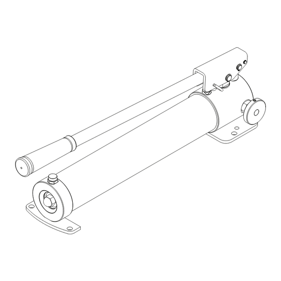
Model No. H3902
E-mail: sales@bvahydraulics.com
Website: www.bvahydraulics.com
Maximum Operating Pressure 10,000 PSI
Model P350
Models P1000 &P1000AD
Approved By:
Checked By:
Drawn By: 蕭益彰 Date: 2016.08.05 File name: H3902_1608OUT
!
This is the safety alert symbol. It is used to alert you to potential personal injury hazards.
Obey all safety messages that follow this symbol to avoid possible injury or death.
Printed in Taiwan
Advertisement
Table of Contents

Related Manuals for BVA P350


Summary of Contents for BVA P350
- Page 1 P350-M0_042018 Hand Pump Instruction Manual MODELS: P350, P1000, & P1000AD SFA Companies 10939 N. Pomona Ave. Kansas City, MO 64153 Tel: 888-332-6419 Fax: 816-448-2142 Model No. H3902 E-mail: sales@bvahydraulics.com Website: www.bvahydraulics.com Maximum Operating Pressure 10,000 PSI Model P350 Models P1000 &P1000AD...
-
Page 2: Safety And General Information
PRODUCT DESCRIPTION BVA Hydraulic Hand Pumps are engineered to meet most industrial standards for performance and safety. P1000AD has a unique two- stage hydraulic circuit which allows quick displacement of hydraulic fluid under no load conditions and easy pumping in loaded conditions. -
Page 3: Specifications
Capacity Capacity with Stroke Outlet Number Type Force (lbs) (in³) (in³) Cylinder (in) Port (lbs) Stage Stage Stage Stage 1/4"- P350 24.9 21.4 0.05 0.38 18NPTF Single 10,000 P1000 Speed 67.1 61.0 Acting 13.7 3/8"- 0.81 0.14 0.82 18NPTF P1000AD 67.1... -
Page 4: Operation
3. Install a pressure gauge in-line from the pump for better control and its components and safety purpose. 4. Close release valve by turning it clockwise. Finger tight ONLY. NOTICE: It is recommended to use BVA fittings, gauge adapter Using tools on release valve can damage it and cause the and guage. pump to malfunction. -
Page 5: Maintenance
4. Wipe up any spilled fluid and reinstall the vented oil filler plug/ screw. TROUBLESHOOTING GUIDE The following information is intended as an aid in determining if problem exists. Pumps should be repaired only by authorized BVA Service Center. For repair service, contact service center in your area. Symptom Possible Causes... - Page 6 Note: Not all components of the pump are replacement items, but are illustrated as a convenient reference of location and position in the assembly sequence. Parts Illustration Drawn By: 蕭益彰 Note: To ensure safe and reliable performance, replace worn or damaged parts with BVA Hydraulics Authorized Replacement Parts only.
- Page 7 (*) - Indicates items included in, and available only as part of Repair Kit. Repair Kits require special skill, training and equipment to repair. Installation must be done by Authorized Service Center. Contact BVA for list of Authorized Service Centers.
- Page 8 Parts Illustration Model No. H1812 Approved By: Checked By: Drawn By: 陳神佑 Date: 2016.04.12 File name:H1812_1604EXP Note: To ensure safe and reliable performance, replace worn or damaged parts with BVA Hydraulics Authorized Replacement Parts only.
- Page 9 (*) - Indicates items included in, and available only as part of Repair Kit. Repair Kits require special skill, training and equipment to repair. Installation must be done by Authorized Service Center. Contact BVA for list of Authorized Service Centers.
- Page 10 (*) - Indicates items included in, and available only as part of Repair Kit. Repair Kits require special skill, training and equipment to repair. Installation must be done by Authorized Service Center. Contact BVA for list of Authorized Service Centers.
- Page 11 (*) - Indicates items included in, and available only as part of Repair Kit. Repair Kits require special skill, training and equipment to repair. Installation must be done by Authorized Service Center. Contact BVA for list of Authorized Service Centers.
- Page 12 Parts Illustration Model No. H1818 Checked By: Approved By: Drawn By: 陳神佑 Date: 2016.04.12 File name: H1818_1604EXP Note: To ensure safe and reliable performance, replace worn or damaged parts with BVA Hydraulics Authorized Replacement Parts only.
- Page 13 (*) - Indicates items included in, and available only as part of Repair Kit. Repair Kits require special skill, training and equipment to repair. Installation must be done by Authorized Service Center. Contact BVA for list of Authorized Service Centers.
- Page 14 Note: Not all components of the pump are replacement items, but are illustrated as a convenient reference of location and position in the assembly sequence. Parts Illustration No. H18-4-1903-109 Note: To ensure safe and reliable performance, replace worn or damaged parts with BVA Hydraulics Authorized Checked By: Drawn By: 陳神佑 Date: 2016.04.12 File name: H18-4-1903-109_16 Replacement Parts only.
- Page 15 Release Valve Base 512-2-0060-016 Compressing Spring H28-4-4406-108 Piston Ass. 661-2-0040-012 Nylon Frange Nut O-ring H18-3-9918-106 Repair Kit - P1000AD Back-up Ring Note: To ensure safe and reliable performance, replace worn or damaged parts with BVA Hydraulics Authorized Replacement Parts only.
-
Page 16: Limited Lifetime Warranty
This warranty does not cover ordinary wear and tear, overloading, alterations (including repairs or attempted repairs not performed by BVA Hydraulics or one of its authorized personnel), improper fluid use, or use of the product in any manner for which the product was not intended or the use of which is not in accordance with the instructions or warnings provided with the product.