
Subscribe to Our Youtube Channel
Related Manuals for Ramsey Electronics COM3010


Summary of Contents for Ramsey Electronics COM3010
- Page 1 USER GUIDE JANUARY, 2005 V1.20.18 Property of Ramsey Electronics, Inc. Do not reproduce or distribute. COM3010 SERVICE MONITOR Copyright Ramsey Electronics, Inc. 2005, All rights reserved...
-
Page 2: Table Of Contents
1.01.01 Checking Contents..................6 1.01.02 Plugging in the Battery ................6 1.01.03 Important Battery Information ...............6 • 1.02 COM3010 Overview ....................8 1.02.01 Front Panel Inputs, Outputs, and Controls..........8 1.02.02 Rear Panel Connections................. 10 1.02.03 Field Selection and Entry ............... 12 2.00 Basic Operation ......................13 •... - Page 3 5.20 Calibrate the Master Time Base ................ 72 • 5.30 Calibrate the Modulation Meter................ 74 6.00 Detailed information....................75 • 6.10 Digital Modulation on the COM3010.............. 76 • 6.20 Advanced Power Meter Information ............... 77 • 6.30 30 dB Rear Panel Attenuator Output .............. 78 •...
- Page 4 APPENDIX B: CTS Tone Frequency List ..............96 • APPENDIX C: DCS Code List..................96 • APPENDIX D: Two Tone Modes .................. 97 • APPENDIX E: General Options Table ................. 97 Specifications .......................... 98 Warranty ..........................100 Property of Ramsey Electronics, Inc. Do not reproduce or distribute.
-
Page 5: Introduction
Property of Ramsey Electronics, Inc. 1.00 INTRODUCTION Do not reproduce or distribute. -
Page 6: Opening The Box
If you are performing extended high power testing the power on the COM3010 may shut off if the unit gets too hot. This is to prevent significant problems with the batteries; the temperature circuit should not be compromised. - Page 7 All three batteries are internally connected in parallel. If you are adding another battery pack to an existing unit, discharge the already installed batteries fully by leaving the COM3010 on until it powers itself off. Only then it is safe to add the new battery pack. Otherwise the new battery arrival may be charged at too fast a rate by the battery already installed and possible damage to the battery could occur.
-
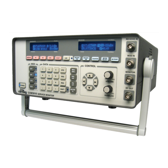
Page 8: Front Panel Inputs, Outputs, And Controls
WARNING! The RECEIVE IN jack is fuse protected using “sacrificial” parts up to 2 watts for a short period of time. This input is not designed to handle high powers! That is reserved for the GENERATE OUT jack. If you accidentally key too much power into this input, the COM3010 will be damaged! This input also has a 1.5dB attenuator in line to allow for a better antenna match to the first... - Page 9 INTRODUCTION and tone generation of the COM3010 is desired. This input can be set to a wide range of sig- nal levels as the built-in AGC will change the gain to get a very specific level before modulat- ing the RF out. This input range should be kept between 50mV pk/pk to 5V pk/pk.
-
Page 10: Rear Panel Connections
Fuse for AC line power. Replace with a standard 1A slow-blow fuse only. L. AC Input There is a 15VDC switching power supply internal to the COM3010 that can operate from a wide range of AC voltages without having to set any jumpers. The power supply included can handle a range from100 VAC to 240 VAC 50/60 Hz. - Page 11 If this gets too hot, it may cause power supply of the COM3010 to shut down to protect the batteries from overheating. If performing a lot of power testing, it wouldn’t hurt to direct air flow at the heat sink to keep it cool, though under normal testing circumstances, this will never be a problem.
-
Page 12: Field Selection And Entry
Field 1 is accessed through the GENERATE key. Field 2 is accessed through the FM key. Field 3 is accessed through the LEVEL key. Field 4 is accessed through the COUNT key. Property of Ramsey Electronics, Inc. RECEIVE Level Meters Do not reproduce or distribute. -
Page 13: Basic Operation
Property of Ramsey Electronics, Inc. Do not reproduce or distribute. 2.00 BASIC OPERATION... -
Page 14: Generating A Frequency
Seq/Reg Enter the frequency desired by using the numerical keypad. Use either the MHz/-dBm kHz/mV key to select your desired units. The COM3010 is now generating the frequency you entered. Example: Property of Ramsey Electronics, Inc. 2.02 Setting Frequency Steps/Increments... -
Page 15: Setting Generator Level
To enter the Level Press the LEVEL key. The “L” Icon will flash. Enter the Level using the keypad, then press your desired units. The COM3010 is now generating your desired level. Example: To cancel an entry, press Property of Ramsey Electronics, Inc. -
Page 16: Muting The Generator
This sets the generator level to – 140dBm as well as setting the generator to its Modulation Seq/Reg lowest possible level. Example: Your Notes: Property of Ramsey Electronics, Inc. Do not reproduce or distribute. -
Page 17: Modulating The Carrier
TX Level Property of Ramsey Electronics, Inc. LED next to the key will light and the COM3010 will display the last deviation used which is indicated by the FMi icon (stands for Modulation Seq/Reg FM internal), and the last tone used indicated by the T icon. - Page 18 Modulation Seq/Reg To enter a new AM value of 50%, press AM, 5, 0, ENTER/%. The COM3010 will now be generating AM with 50% modulation and a 1 kHz tone. Example: Your Notes: Property of Ramsey Electronics, Inc.
-
Page 19: Generating Using External Mod In
AGC (automatic gain control). Any level from an external generator between 100mV and 2V peak will be compensated with the AGC circuit. Remember there are three types of AGC supported by the COM3010. These three modes are cycled using SHIFT, EXT. -
Page 20: Generating Cts
Example: To enter a new CTS frequency of 78.5Hz, press The tone may be toggled on and off by pressing Property of Ramsey Electronics, Inc. To enter a deviation value, press Do not reproduce or distribute. to select the FM field; the icon will blink. To enter a deviation of 300.0Hz, press Standard CTS deviation is typically 0.75 kHz. -
Page 21: Generating Dcs
You must enter the DCS code with the UP / DOWN keys. You will be selecting from an internal list stored in the COM3010. To select a code of 53, use the keys to select the code. For inverted digital code, press SHIFT, DCS;... -
Page 22: Modulation Steps
For AM press SHIFT, AM and enter a value from 1% to 50% followed by ENTER / % Property of Ramsey Electronics, Inc. Example: To enter a value of 10%, press Do not reproduce or distribute. To cancel out press... -
Page 23: Generating Two-Tone Paging Signals
BASIC OPERATION 2.06.06 Generating Two-Tone Paging Signals The COM3010 can also generate two tone sequential paging signals. Because there are two tones involved, both displays are used with their corresponding function keys. It is important to remember that each of the display fields is controlled by a specific function key. The 2nd... - Page 24 You wish to generate a typical two-tone, tone only paging signal. Tone one is 349.0 Hz, and tone-two is 433.7 Hz. Sets tone one to 349 Hz. Property of Ramsey Electronics, Inc. Sets tone two to 433.7 Hz. Do not reproduce or distribute.
-
Page 25: Receiving A Frequency
2.08 Setting a Receiver Step/Increment Rather than having to move the cursor to a RECEIVE Level Meters specific digit to increment frequency, the COM3010 employs increments for important fields. To access an increment for the field of Counter Freq Meters interest, press... -
Page 26: Using The Frequency Counters
Property of Ramsey Electronics, Inc. Used for measuring signals in the lower Counter, 100Hz-70 0.1s frequency range of the COM3010. Does not use a Do not reproduce or distribute. frequency prescaler so accuracy is 1Hz maximum. Worst case sensitivity of 10mV. Only displays Counter, 100 Hz-70 1.0s... -
Page 27: Using The Frequency Meters
Example: To select meter mode To zoom a display for easy viewing COM3010 Meter Displays Property of Ramsey Electronics, Inc. FM Mode: Meter Displayed Description 2.10.01 This meter displays the instantaneous modulation packet showing the minimum and maximum level. It displays... -
Page 28: Frequency Error Bargraph, Positive
2.10.06 The frequency error bargraph allows visual calibra- tion of a frequency reference to the internal reference of the COM3010. This is scale-1, error positive. For a more precise Frequency Error Bargraph error value see the Digital Frequency Error meter below. -
Page 29: Using The Level Meters
Meter input to COM3010 is 100 Watts. 2.11.04 Displays the current battery state. Low end of battery is at 10.0V and high end is at 12.6V. The COM3010 will power itself off below 10.0V to preserve the battery. Battery Meter 2.11.05 Displays the status of the serial port while communi-... -
Page 30: Zooming The Frequency Meters
Freq Meters In the modulation meter above, each large tick represents 1 kHz, so the meter is reading – Property of Ramsey Electronics, Inc. 3.2/+3.5 kHz of deviation. If you want numbers instead switch to the text version of this me-... - Page 31 GENERATE TX Level RECEIVE Level Meters Modulation Seq/Reg Counter Freq Meters Property of Ramsey Electronics, Inc. This is an example of the zoomed audio frequency counter and the RSSI meter. Your Notes: Do not reproduce or distribute.
- Page 32 Your Notes: Property of Ramsey Electronics, Inc. Do not reproduce or distribute.
-
Page 33: Typical Test Procedures
Property of Ramsey Electronics, Inc. Do not reproduce or distribute. 3.00 TYPICAL TEST PROCEDURES... - Page 34 This section outlines typical measurements that can be made with the COM3010. These test procedures are basic ones designed to help you get familiar with the unit. Once familiar with the COM3010 you will be able to combine and modify these procedures to fit your own op- eration, increasing its efficiency.
-
Page 35: Transmitter Tests
Warning - Do not under any circumstances connect a transmitter to the RECEIVE IN jack of the COM3010, or damage will result! Warning - Maximum RF power input to the RF OUT jack of the COM3010 is 100 W. Do not exceed this level or damage will result! Property of Ramsey Electronics, Inc. - Page 36 TYPICAL TEST PROCEDURES Frequency Error Measurement The COM3010 will also display the Counted Frequency (Lower left field) and The Frequency Error (lower right field) in the RECEIVE screen. Press to Zoom the Frequency Error meter to the entire RECEIVE screen.
-
Page 37: Power Measurements
Do not reproduce or distribute. The COM3010 will automatically switch to Power Meter mode when the radio is keyed, or, to enter Power Meter mode manually, press SHIFT, Key the radio; the power reading is displayed in the Generate screen. - Page 38 TYPICAL TEST PROCEDURES 3.10.02 Power Measurements (Continued) Key the radio into the COM3010; the frequency counter will begin to count the RF signal. The text to the right of the power meter will show “POWER GOOD” to indicate that the count value and calibration are correct.
-
Page 39: Frequency Counter Off-Air
Do not reproduce or distribute. Setting the step size to the channel size causes the COM3010 to set the Receiver or Generator to the channel frequency, not the counted frequency, which is important if the radio being tested is off frequency. The rounding function can be toggled on and off in the Options Menu. -
Page 40: Cts Tone Frequency And Deviation Measurement
1 Hz. After a period of 10 seconds the resolution accuracy will increase to 0.1Hz . Example: A transmitter has a CTS tone of 123.4Hz. The user keys the radio into the COM3010 as above. The first count will read 123.0Hz, the second, 123.1Hz, the third, 123.2Hz… and after ten counts, 123.4Hz. -
Page 41: Receiver Tests
For more precise sensitivity measurements see “3.20.02 SINAD Measurements”. Receiver Sensitivity Connect a test cable between the COM3010 RF OUT jack and the receiver to be tested. Set the receiver to be tested to the desired test frequency. See the receiver’s owners manual. -
Page 42: Sinad Measurements
0.1 uV steps. Set the FM Deviation to 60% of the maximum allowable signal for the band. Example: For the 5 kHz band set the COM3010’s deviation for 3 kHz (5000 * 0.6 = 3000). Select SHIFT, 8... - Page 43 The AGC cannot bring the level up high enough to compensate. Property of Ramsey Electronics, Inc. When the icon indicates the up arrow it means the audio level is too great for the AGC to compensate. You will need to turn down the audio control or reduce the modulation used.
-
Page 44: Opening Receiver Squelch Using Cts
The following procedure allows the technician to open a receiver’s CTS encoded squelch. The Service Monitor uses “sub-audible” tones, usually under 300Hz at ±0.5 kHz of deviation. Connect a test cable between the COM3010’s RF OUT jack and the receiver under test’s antenna jack. -
Page 45: Opening Receiver Squelch Using Dcs
Opening a receivers DCS encoded squelch can be achieved by using the following procedure. The COM3010 supports all the commonly used codes, both non-inverted (N) and inverted (I). Connect a test cable between the COM3010’s RF OUT jack and the receiver under test’s antenna jack. -
Page 46: Two-Tone Paging
TYPICAL TEST PROCEDURES 3.20.05 Two-Tone Paging This function allows the COM3010 user to open the squelch of a receiver using the Two-Tone Paging format. Connect a whip antenna on the generator RF OUT of the COM3010. Set Generate frequency. Example Enter desired RF Level. -
Page 47: Sending External Modulation
DC coupled to allow proper transmission of digital data as well as accurate reproduc- tion of 4-level paging formats such as FLEX. The COM3010’s AGC circuit takes whatever signal is seen on the MOD IN jack and amplifies it to a specific value to produce the proper modulation output. - Page 48 “Low” increase the audio input level. If it displays “Adj” it is internally adjusting the au- dio level to give the proper output modulation. The COM3010 is now transmitting the tone at the requested frequency and modula- tion. Your Notes:...
- Page 49 1 Vpp. Set the generator for desired RF frequency. Example: 464.15 MHz, Press Turn on external deviation by pressing Property of Ramsey Electronics, Inc. Select the tone AGC mode by pressing until you see the square wave icon.
-
Page 50: Testing Repeater Receiver Desensitization
They are occasionally found in the 150-160 MHz VHF bands as well. The COM3010, with its high stability accurate signal source using a calibrated isolator T connector allows you to accurately and quickly verify correct duplexer operation. It is also very easy to check Receiver Desensitization or what’s often referred to as Receiver Desens. - Page 51 This will be approximately -115dBm. Remember to calculate the actual value you are setting the COM3010 to an output level that is 40 dB greater due to the insertion loss of the T. Since you have already calibrated the isolator T for 40 dB of insertion loss you simply add the loss to the generator output to arrive at the repeater’s true sensitivity.
- Page 52 Typical readings are usually no more than 1 – 3 dB of measurable desensitization. ANTENNA FIGURE-2 DESENS TEST SETUP 40 DB CALIBRATED ISOLATOR T ADAPTER (ISO-T) SET COM3010 TO REPEATER RX FREQ Property of Ramsey Electronics, Inc. TX PASS TX PASS RX PASS RX PASS Do not reproduce or distribute.
-
Page 53: Tuning A Duplexer
Check the manufacturer’s specifications to make sure that you are tuning a Band Reject duplexer. IMPORTANT NOTES: Property of Ramsey Electronics, Inc. • Be sure the cables used for duplexer testing are of high quality double shielded type with the proper connectors. - Page 54 Attach the 50 Ohm load directly to the duplexer transmitter port. Connect the RECEIVE IN to the duplexer receiver port. Property of Ramsey Electronics, Inc. The receiver in the RSSI mode is now connected. Adjust the cavity closest to the RECEIVE IN connection for minimum signal or greatest notch.
- Page 55 IMPORTANT: REPEAT STEPS 1 AND 2 UNTIL NO FURTHER IMPROVEMENT IN DUPLEXER ISOLATION CAN BE ACHIEVED. FIGURE-2 TX PASS – TRANSMITTER SIDE SET COM3010 TO REPEATER TX FREQ TX PASS TX PASS RX PASS RX PASS TUNE TO NOTCH RX...
- Page 56 You can now determine the receiver insertion loss in db by adding the generator dbm value to the RSSI value. Example Generator – 90 dbm and Receiver RSSI – 91.5 dbm = Property of Ramsey Electronics, Inc. 1.5 db insertion loss. It should also be close to the manufacturer’s specifications.
-
Page 57: Advanced Features
Property of Ramsey Electronics, Inc. Do not reproduce or distribute. 4.00 ADVANCED FEATURES... -
Page 58: Memories
The COM3010 provides safeguards that allow for ease of use and prevent accidentally overwriting another memory location. For example, when saving a register to a sequence that has memories stored in it, the COM3010 will select the first empty register available. The Property of Ramsey Electronics, Inc. - Page 59 Press Enter the two digit register number or Use the Up/Down arrows to scroll through different registers. Property of Ramsey Electronics, Inc. Copying Registers Recall the sequence and register to be moved, then the sequence and register to be copied to. Example: Sequence 5, register 13 copied to sequence 7, register 13.
- Page 60 If a new power-up setting is desired, set the Generate and Receive screens as required and save your new power-up default as normal using SEQ 99 REG 99. This can be overwritten at any time, or deleted it to return to the COM3010’s original default power-up state.
-
Page 61: Smart Link
For example you can set the Generator frequency to 464.55 MHz, using this sequence: For a 25 kHz offset in the receiver, add 25 kHz to the Generate frequency to get 464.575 MHz. Property of Ramsey Electronics, Inc. Next press: and the value of 25 kHz is entered as the offset. -
Page 62: Scanner
The scanner function is used to monitor known frequencies for proper operation. The scanner function will allow sweeping through any sequence of memories that are pre- programmed into the COM3010. This allows scanning of up to100 channels in a single sweep. The more channels stored, the longer the scan times. - Page 63 This is due to the broad channel discrimination of the COM3010. To remedy this, set the squelch a bit tighter to reject the adjacent channels and open only on the stronger RSSI signal.
-
Page 64: Sweep Generator
COM3010 will display an error telling you that some of the points will not be swept. The remedy is to reduce the Generate Frequency step size before sweeping. - Page 65 100 steps, follow these keystrokes: To enter the sweep function, press SHIFT,1. Enter 10 MHz in the BE field. Property of Ramsey Electronics, Inc. Enter 1000 MHz in the FB field. Do not reproduce or distribute. Set LEVEL to –120 dBm.
-
Page 66: User Options
The options listed that are available to the user are in brackets. The options between the ‘<‘ ‘>‘ signs are password protected and only available to qualified COM3010 service technicians. The reason for this is that modifying these options can change or erase unit calibrations that only a qualified COM3010 technician with appropriate calibrated test equipment can properly adjust. - Page 67 Password security on the Do not reproduce or distribute. COM3010 is tight! If you forget your password the only way to unlock the COM3010 is to send it in for repair! The standard repair fee applies for Ramsey to reset the password. As...
- Page 68 Choices Default Description Port Name: Baud 300, 600, 1200, 57600 Sets the Baud Rate of the COM3010 Serial Port, 2400,4800, always defaults in 8,n,1 communications. 9600, 14400, 9200,28800, 57600, 115200 Address 000 to 999 Allows user to view or change the Serial Port Ad-...
-
Page 69: Battery Power Saver
Clear Memories is an option that allows you to clear all registers and sequences including the special 99.99 registers. This allows you to “clean up” the COM3010 if planning on setting it up for a new test bench or other purpose. - Page 70 Your Notes: Property of Ramsey Electronics, Inc. Do not reproduce or distribute.
-
Page 71: Calibrations
Property of Ramsey Electronics, Inc. Do not reproduce or distribute. 5.00 USER CALIBRATIONS... -
Page 72: Calibrate The Rssi Meter
This table will then be stored in the COM3010’s Flash Memory for later use. The RSSI meter can display any level between –40dBm and -120dBm to an accuracy of ± 1 dB. -
Page 73: Calibrate The Master Time Base
Freq Meters 5.20 Calibrate the Master Time Base The COM3010’s Master Time Base is a voltage controlled TCXO with an accuracy of better than ± 0.1ppm over a given time and temperature. The time base is easily adjusted to any calibrated standard or reference available. - Page 74 USER CALIBRATIONS 5.20 Calibrate the Master Time Base (Continued) Connect an accurate reference frequency source to the COM3010’s RECEIVE IN jack. Press to enter the Main Calibration Menu. Press to select [Freq Ref]. Note the warning about having a good reference.
-
Page 75: Calibrate The Modulation Meter
USER CALIBRATIONS 5.30 Calibrate the Modulation Meter Occasionally the quadrature detector of the COM3010 may need alignment to center the modulation meters. Connect the RF OUT to the RECEIVER IN using a BNC to BNC cable. Press to enter the Main Calibration Menu. - Page 76 Your Notes: Property of Ramsey Electronics, Inc. Do not reproduce or distribute.
-
Page 77: Detailed Information
Property of Ramsey Electronics, Inc. Do not reproduce or distribute. 6.00 DETAILED INFORMATION... -
Page 78: Digital Modulation On The Com3010
Modulation analyzers, however, have extremely wide reception bandwidths of over 1 MHz. They see the audio signals the COM3010 is creating, as well as the digitizing artifacts. The modulation analyzer will record a wider than expected modulation unless the proper low pass filter is selected on the analyzer. -
Page 79: Advanced Power Meter Information
The COM3010 power meter is a voltage mode power meter. The COM3010 power meter is not a true RMS type of power meter, meaning that it will measure your primary carrier voltage accurately and convert it to a power in dBm. It is possible for harmonics and other signals to cause error. -
Page 80: Db Rear Panel Attenuator Output
6.30 30 dB Rear Panel Attenuator Output. The 30dB attenuator output on the back of the COM3010 can be used for a variety of external hookups such as spectrum analyzers, modulation analyzers, and other test gear. It can also be used to loop back into the receiver input on the front to obtain good frequency counts during power testing. -
Page 81: Advanced Sinad Information
In the COM3010 this is provided though FM modulation at 1kHz, or AM modulation at 1kHz, when set in the modulation fields (using Property of Ramsey Electronics, Inc. - Page 82 The COM3010 can amplify fairly low level signals up to a usable level so that you don’t add distortion errors to your measurement by turning up the volume of a radio so high that it ruins the SINAD test reading.
-
Page 83: Rs232 Communications
The serial port on the back of the COM3010 is filtered to prevent RF leakage. This filtering may cause errors at baud rates over 57.6K; therefore, it is best to use 57.6K baud and lower with the COM3010. - Page 84 “>>“. Problems? If the COM3010 does not respond but the Rx light flickers as you type, there can be two pos- sible problems. The first is that you have the COM3010 set to an address other than 555 from a previous session.
- Page 85 4096 bytes in size which will allow for long scripts. There are delay functions to allow measurements to settle or an automated test bench to get operations in place. An example script used for automatic testing can be sent to the COM3010’s serial port as a text file.
-
Page 86: Sys Commands
First address must match old address, second Do not reproduce or distribute. address must be within 0->999 If echo is on, COM3010 ECH/ECHO ON/OFF OK/BAD sends back everything it receives through the RS232 port. TIMEOUT... -
Page 87: Set Commands
SET GL,LVL,LEVEL -###.#dBm -120 OK/BAD SET MEXT ON/OFF OK/BAD Set Mod External SET MINT ON/OFF OK/BAD Set Mod Internal Property of Ramsey Electronics, Inc. SET MCTS ON/OFF OK/BAD Set Mod CTS Set Mod DCS SET MDCS ON/OFF OK/BAD SET MALL Do not reproduce or distribute. - Page 88 Description Com- Command mand ###.#### 0.100000 1000.00000 OK/BAD Set Receiver frequency #MHz Property of Ramsey Electronics, Inc. AM Receive mode FM Receive Mode Set Counter Mode (see COUNTERM OK/BAD Do not reproduce or distribute. counter mode lists) LMETER OK/BAD Set Lower Meter Mode...
-
Page 89: Mem Commands
OK/BAD from sequence.register OK/BAD Recall next memory in the sequence PREV OK/BAD Recall previous memory in the Property of Ramsey Electronics, Inc. sequence Save memory in SAVE ##.## 00.00 99.99 OK/BAD specified sequence.register Do not reproduce or distribute. Delete specified ##.##... -
Page 90: Get Commands
AF counter is selected as one of the meters FMDEV +/-7kHz +#.##kHz/- Get current FM deviation (numerically) #.##kHz Property of Ramsey Electronics, Inc. DELTAF Get frequency error from current receive frequency ####.##### (see counter mode lists) #MHz Do not reproduce or distribute. - Page 91 ###.#dBm Get Generator Level MEXT ON/OFF Get External Modulation State MINT ON/OFF Get Internal Modulation State Property of Ramsey Electronics, Inc. MCTS ON/OFF Get CTS Modulation State MDCS ON/OFF Get DCS Modulation State Do not reproduce or distribute. GAMFM AM/FM/OFF...
- Page 92 Get Lower Meter Mode (See valid meter mode lists) UMETER Get Upper Meter Mode (See valid meter mode lists) POWER ON/OFF Returns the large power METER meter to the display Property of Ramsey Electronics, Inc. Your Notes: Do not reproduce or distribute.
-
Page 93: Various Meter Mode Options
FM Modulation Graphic +/-7kHz FM Modulation Graphic +/-4kHz FM Modulation Text AM Percent Graphic AM Percent Text Audio Frequency Counter Sinad Meter Property of Ramsey Electronics, Inc. Upper Meter Mode Table RSSI Bargraph Do not reproduce or distribute. RSSI Text RF Power... -
Page 94: Various Mode Options
DETAILED INFORMATION 6.50.07 Various Mode Options Sweep Mode Table Decade Octive Linear External AGC Mode Table Tone Voice Digital Sinad Property of Ramsey Electronics, Inc. Sweep Speed Mode Table <10mS Do not reproduce or distribute. 10mS 25mS 50mS 100mS 250mS 500mS... -
Page 95: Appendix
Property of Ramsey Electronics, Inc. Do not reproduce or distribute. 7.00 APPENDIX... -
Page 96: Appendix Abutton Reference Chart
Toggles the internal modula- PAGING Accesses the various paging modes Property of Ramsey Electronics, Inc. tion mode and selects tone. that the COM3010 supports (Two Tone) Toggles CTS tone and selects None tone. Do not reproduce or distribute. - Page 97 Enters a “-” DELETE Deletes current memory Starts memory save None Selects a sequence None Property of Ramsey Electronics, Inc. Selects a register None SHIFT Selects the shift function Do not reproduce or distribute. MHZ/-dBm Enters units for active field GEN ON/OFF Toggles the generator on and off.
-
Page 98: Appendix Bcts Tone Frequency List
127.3 146.2 167.9 192.8 225.7 77.0 88.5 100.0 114.8 131.8 151.4 173.8 203.5 233.6 Property of Ramsey Electronics, Inc. APPENDIX C DCS CODE LIST: Do not reproduce or distribute. 023N 074N 165N 261N 364N 464N 631N 025N 114N 172N 263N... -
Page 99: Appendix Dtwo Tone Modes
1.3 Seconds Battery Save 2.7 Seconds 0.8 Seconds 1.3 Seconds Group Call 0 Seconds (Not sent) 8 Seconds 1.3 Seconds Property of Ramsey Electronics, Inc. APPENDIX E Do not reproduce or distribute. GENERAL OPTIONS TABLE Option Choices Default Description Name:... -
Page 100: Specifications
Attenuator Output: -30 dB attenuator output from internal load for monitoring • Calibrated RSSI Meter: 80 dB of range on receiver side., -40 dBm to -120 dBm Generate: Property of Ramsey Electronics, Inc. • Frequency: 100 kHz to 1.0 GHz, 1 Hz steps •... - Page 101 Frequency Range: 60 Hz to 3000 Hz • Gates: 10 Sec variable gate for 1 Sec quick updates • Sensitivity: 35 mV at demod audio, 750 Hz deviation Property of Ramsey Electronics, Inc. Frequency counter: • Frequency Range: 100 kHz to 1.0 GHz •...
- Page 102 Accessories: • Battery Pack: BP3010 additional battery pack to extend battery life (1 pack supplied, 3 max) • Carrying Case: CC3010 custom Cordura® padded travel case w/ strap Property of Ramsey Electronics, Inc. Do not reproduce or distribute.
-
Page 103: Warranty
Tech Support will help you diagnose your problem and, if necessary, issue an RMA for the return of your COM3010. Equipment cannot be returned without a proper RMA number. With your return, please include specific descriptions of the problem encountered as well as detailed contact information including daytime telephone number, E-Mail address, and complete return shipping address information. - Page 104 Property of Ramsey Electronics, Inc. Do not reproduce or distribute. RAMSEY ELECTRONICS, INC. 590 Fishers Station Drive COM3010 Victor, NY 14564 (585) 924-4560 January 2005 www.ramseytest.com V1.20.18 Copyright Ramsey Electronics, Inc. 2005, All rights reserved...
Need help?
Do you have a question about the COM3010 and is the answer not in the manual?
Questions and answers