Metos CHEF 220 Installation And Operation Manual
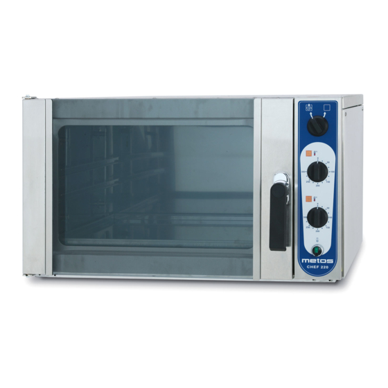
Roasting-baking oven
Hide thumbs
Also See for CHEF 220:
- Installation and operation manual (34 pages) ,
- Installation and operation manual (52 pages)

Subscribe to Our Youtube Channel
Related Manuals for Metos CHEF 220


Summary of Contents for Metos CHEF 220
- Page 1 ROASTING-BAKING OVEN CHEF 220 Installation and Operation Manual S/N: 095323/02 Valid from: 01. 06. 2009 Rev.: 3.0...
- Page 3 Dear Customer, Congratulations on deciding to choose a Metos appliance for your kitchen activities. You made an excellent choice. We will do our best to make you a satisfied Metos customer like thousands of customers we have around the world.
- Page 4 25.6.2009 Rev. 3.0...
-
Page 5: Table Of Contents
25.6.2009 Rev. 1. General ......................1 1.1 Symbols used in the manual ..................1 1.2 Symbols used on the appliance ..................1 1.3 Checking the relationship of the appliance and the manual .......... 1 2. Safety ......................2 2.1 Safe use of the appliance ....................2 2.2 Disposal of the appliance .................... - Page 6 25.6.2009 Rev. 5.5 Test-run ........................13 6. Troubleshooting ..................14 7. Spare parts ....................15 7.1 Voltage codes ......................17 7.2 Product codes ....................... 17 8. Technical specifications ................29...
-
Page 7: General
25.6.2009 Rev. 3.0 General 1. General Carefully read the instructions in this manual as they contain important information re- garding proper, efficient and safe installation, use and maintenance of the appliance. Keep this manual in a safe place for eventual use by other operators of the appliance. The installation of this appliance must be carried out in accordance with the manufactur- er’s instructions and following local regulations. -
Page 8: Safety
25.6.2009 Rev. 3.0 Safety 2. Safety 2.1 Safe use of the appliance An oven is a warming device which heats up when used. For this reason, please observe the following instructions to avoid the risk of burns. The glass and edges of the door also become hot when the oven is used for longer periods. Use oven gloves when handling hot ovenware and baking plates. -
Page 9: Functional Description
One or two ovens can also be replaced by a Chef 240 convection oven or a Chef 200 proving cabinet. This manual covers the Chef 220 convection oven, while Chef 240 and Chef 200 have their own manuals. -
Page 10: Control Panel Switches
Rev. 3.0 Functional description 3.3.1 Control panel switches Control panel switches Chef 220 Steam exhaust valve. The valve can be used to remove excess steam and moisture from inside the oven. Upper heating on - thermostat lamp. The yellow lamp is on when the heat- ing elements are on. -
Page 11: Operation Instructions
25.6.2009 Rev. 3.0 Operation instructions 4. Operation instructions 4.1 Before using the appliance There is a slight smell of metal and thermal insulation when the oven is heated for the first time. This is completely normal and disappears by heating the oven. Before using the oven for the first time, heat it to a temperature of +250ºC until the smell disappears. -
Page 12: Operation Procedures
25.6.2009 Rev. 3.0 Operation instructions 4.2 Operation procedures 4.2.1 Before cooking The oven must be preheated to cooking temperature before actual cooking begins. This is to heat the whole oven to the correct temperature so as to ensure the best possible cooking results. -
Page 13: Steam Removal
25.6.2009 Rev. 3.0 Operation instructions In the event of longish interruptions in the electricity supply when the oven is in use, turn all switches to the 0 position to prevent the oven from coming on unexpectedly when the power cut has ended. 4.2.5 Steam removal The steam exhaust valve (see Figure “Control panel switches”) is normally closed to pre- vent moisture from being lost from inside the oven. - Page 14 25.6.2009 Rev. 3.0 Operation instructions Type Oven- Pre- Cooking tem- Cooking Tips food ware heat- perature time Casseroles GN 1/1- 175-200ºC 1,5-2,0 h We suggest a lower cooking temperature for 65 mm egg-based casseroles than for other casseroles Volume: about 5 kg per dish Macaroni and 200ºC 175ºC...
-
Page 15: After Use
25.6.2009 Rev. 3.0 Operation instructions 4.3 After use 4.3.1 Cleaning Use of a hose or pressure washer to clean the appliance is forbidden. Before cleaning the oven, please remember that it remains hot for a long time after use. Ovens are electrical appliances, which means that there are restrictions regarding cleaning them with water. -
Page 16: How To Change The Oven Bulb
25.6.2009 Rev. 3.0 Operation instructions Cleaning of external surfaces of the door The external glass of the door can be opened for cleaning. Unscrew the two screws shown in the picture and turn the external glass carefully downward until it stays fully open. Spray diluted detergent solution onto the door’s metal surfaces between the glasses and onto the glass surfaces. -
Page 17: Installation
25.6.2009 Rev. 3.0 Installation 5. Installation 5.1 General The installation of this appliance must be carried out in accordance with the manufactur- er’s instructions and in compliance with local rules and regulations. These instructions must be used together with the installation drawing. This appliance may be connected to the mains electricity by qualified persons only. -
Page 18: Installation Of A Chef Oven Group
25.6.2009 Rev. 3.0 Installation 5.2.2 Installation of a Chef oven group The appliances can be assembled to form combinations of two or three units by stacking them on top of each other. The stand height for two units is 660 mm and for three units 200 mm. -
Page 19: Test-Run
25.6.2009 Rev. 3.0 Installation 5.5 Test-run Please read the safety and operation instructions as well as the functional description be- fore testing the oven. As for other appliances possibly included in the roasting and baking station, see separate manuals. Test the oven once it has been connected to the mains electricity. Check that •... -
Page 20: Troubleshooting
25.6.2009 Rev. 3.0 Troubleshooting 6. Troubleshooting If the appliance fails to work, check to ensure that • it has been used according to instructions • all removable parts are in place • the disconnection switch (usually on a wall or in the immediate vicinity of the ov- en) is in the ON position •... -
Page 21: Spare Parts
25.6.2009 Rev. 3.0 Spare parts 7. Spare parts General parts ........19 Heating, Steam exhaust......23 Control unit........... 25... - Page 22 25.6.2009 Rev. 3.0 Spare parts...
-
Page 23: Voltage Codes
2/PE 220−240V 50Hz 3/N/PE∼415/240V 50Hz 3/PE∼230V 50Hz 3/PE∼220V 60Hz 3/PE∼380 50Hz 3/PE∼400V 50Hz 3/PE∼415V 50Hz 3/PE∼440V 60Hz 3/PE∼460V 60Hz 3/PE∼480V 60Hz 1/N/PE~220-240V 50Hz 2/PE~220-230V 60Hz 3/N/PE∼400/230V 50Hz 3/PE∼230V 60Hz 1/N/PE~100V 50-60Hz 7.2 Product codes Product code Full name Model codes CHEF 220... - Page 24 25.6.2009 Rev. 3.0 Spare parts...
- Page 25 3323458 Seal 3752055 Bottom plate 3752052 Drip collector 3752253 2 guide rails 3440874 Fixing pin for guide rails 3444163 Washer 22=CHEF 220 A=3/N/PE∼400/230V 50Hz, C=3/N/PE∼380/220V 50Hz, G=3/N/PE∼415/240V 50Hz, H=3/PE∼230V 50Hz, I=3/PE∼220V 60Hz, J=3/PE∼380 50Hz, K=3/PE∼400V 50Hz, L=3/PE∼415V 50Hz, M=3/PE∼440V 60Hz...
- Page 26 25.6.2009 Rev. 3.0 Spare parts...
- Page 27 Screw 3751891 Side panel 3752250 J,K,L,M Side panel (Marine) 3751691 Backside panel 3752251 J,K,L,M Backside panel (Marine) 3592789 Steam outlet 22=CHEF 220 A=3/N/PE∼400/230V 50Hz, C=3/N/PE∼380/220V 50Hz, G=3/N/PE∼415/240V 50Hz, H=3/PE∼230V 50Hz, I=3/PE∼220V 60Hz, J=3/PE∼380 50Hz, K=3/PE∼400V 50Hz, L=3/PE∼415V 50Hz, M=3/PE∼440V 60Hz...
- Page 28 25.6.2009 Rev. 3.0 Spare parts...
- Page 29 3399551 Lower plate 3751636 Steam outlet pipe 3440666 Valve 3590534 3021792 Washer 3285379 Cotter pin 3751621 Bracket 3591111 Flexible axle 22=CHEF 220 A=3/N/PE∼400/230V 50Hz, C=3/N/PE∼380/220V 50Hz, G=3/N/PE∼415/240V 50Hz, H=3/PE∼230V 50Hz, I=3/PE∼220V 60Hz, J=3/PE∼380 50Hz, K=3/PE∼400V 50Hz, L=3/PE∼415V 50Hz, M=3/PE∼440V 60Hz...
- Page 30 25.6.2009 Rev. 3.0 Spare parts...
- Page 31 3493234 Knob 3752046 Switch, S1 3752048 Fixing adapter 3752049 LED block 3752050 Contact block 3442141 Pilot lamp, yellow H1, H2 22=CHEF 220 A=3/N/PE∼400/230V 50Hz, C=3/N/PE∼380/220V 50Hz, G=3/N/PE∼415/240V 50Hz, H=3/PE∼230V 50Hz, I=3/PE∼220V 60Hz, J=3/PE∼380 50Hz, K=3/PE∼400V 50Hz, L=3/PE∼415V 50Hz, M=3/PE∼440V 60Hz...
- Page 32 25.6.2009 Rev. 3.0 Spare parts...
- Page 33 Terminal block 125120.11 M10/10N K382550 Cable gland 3752329 A,C,G,H,I Set of wires 3752149 J,K,L,M Set of wires 3751613 Components support 22=CHEF 220 A=3/N/PE∼400/230V 50Hz, C=3/N/PE∼380/220V 50Hz, G=3/N/PE∼415/240V 50Hz, H=3/PE∼230V 50Hz, I=3/PE∼220V 60Hz, J=3/PE∼380 50Hz, K=3/PE∼400V 50Hz, L=3/PE∼415V 50Hz, M=3/PE∼440V 60Hz...
- Page 34 25.6.2009 Rev. 3.0 Spare parts...
-
Page 35: Technical Specifications
25.6.2009 Rev. 3.0 Technical specifications 8. Technical specifications Main and control circuit 83689 D83 Main and control circuit S00012 A3 Connection diagram S00005 D3 Main and control circuit S00002 B3 Main and control circuit S00019 B3 Connection diagram S00008 C3 Connection diagram T01701 A3 Installation drawing T01578 A3 Installation drawing T01593 A3... - Page 36 Main and control circuit 83689 D83...
- Page 37 Main and control circuit S00012 A3...
- Page 38 Connection diagram S00005 D3...
- Page 39 Main and control circuit S00002 B3...
- Page 40 Main and control circuit S00019 B3...
- Page 41 Connection diagram S00008 C3...
- Page 42 Connection diagram T01701 A3...
- Page 43 Installation drawing T01578 A3...
- Page 44 Installation drawing T01593 A3...
- Page 45 Installation drawing T01594 B3...
- Page 46 Installation drawing T01595 B3...
- Page 47 Installation drawing T01597 B3...
- Page 48 Installation drawing T01596 B3...
- Page 49 Stand Metos 2928 Marine (height 660mm) Stand Metos 2928 with 10 pcs. GN1/1 guide rails Stand Metos 2928 with wheels Stand Metos 2928 with wheels and 10 pcs. guide rails Stand Metos 2908 (height 200mm) Stand Metos 2908 Marine (height 200mm) 22=CHEF 220 A=3/N/PE∼400/230V 50Hz, C=3/N/PE∼380/220V 50Hz, G=3/N/PE∼415/240V 50Hz, H=3/PE∼230V 50Hz, I=3/PE∼220V...
- Page 50 VALUKOJA 16...
- Page 51 PROVING CABINET CHEF 200 Installation and Operation Manual S/N: 085317/01 Valid from: 05. 05. 2008 Rev.: 3.0...
- Page 53 Dear Customer, Congratulations on deciding to choose a Metos appliance for your kitchen activities. You made an excellent choice. We will do our best to make you a satisfied Metos customer like thousands of customers we have around the world.
- Page 54 7.7.2008 Rev. 3.0...
- Page 55 7.7.2008 Rev. 1. General ......................1 1.1 Symbols used in the manual ..................1 1.2 Symbols used on the appliance ..................1 1.3 Checking the relationship of the appliance and the manual .......... 1 2. Safety ......................2 2.1 Safe use of the appliance ....................2 2.2 Disposal of the appliance ....................
- Page 56 7.7.2008 Rev. 6. Troubleshooting ..................13 7. Spare parts ....................15 7.1 Voltage codes ......................17 7.2 Product codes ....................... 17 8. Technical specifications ................29...
-
Page 57: General
7.7.2008 Rev. 3.0 General 1. General Carefully read the instructions in this manual as they contain important information re- garding proper, efficient and safe installation, use and maintenance of the appliance. Keep this manual in a safe place for eventual use by other operators of the appliance. The installation of this appliance must be carried out in accordance with the manufactur- er’s instructions and following local regulations. -
Page 58: Safety
7.7.2008 Rev. 3.0 Safety 2. Safety 2.1 Safe use of the appliance Do not leave the proving cabinet on completely unattended for long periods. The water basin in front of the fan inside the proving cabinet must be kept in the proper position when the proving cabinet is in use. -
Page 59: Functional Description
One or two proving cabinets can also be replaced by a convection oven or a roasting-baking oven. This manual covers the Chef 200 proving cabinet, while Chef 240 and Chef 220 have their own manuals. -
Page 60: Control Panel Switches
7.7.2008 Rev. 3.0 Functional description 3.3.1 Control panel switches Control panel switches Chef 200 Moistening lamp. The yellow lamp is always on when the water basin’s heating element is on. The lamp goes out when the temperature required by the humidity-% has been reached. Moistening device. -
Page 61: Operation Instructions
7.7.2008 Rev. 3.0 Operation instructions 4. Operation instructions 4.1 Before using the appliance There is a slight smell of metal and thermal insulation when the proving cabinet is heated for the first time. This is completely normal and disappears by heating the proving cabi- net. -
Page 62: Proving
7.7.2008 Rev. 3.0 Operation instructions 4.2.4 Proving • Carefully preheat the proving cabinet as instructed in “Before proving”. • Turn the handle to open the proving cabinet door. To close the door, push the han- dle until you hear a distinct click. •... -
Page 63: Weekly Cleaning
7.7.2008 Rev. 3.0 Operation instructions Weekly cleaning Spray diluted detergent solution into the inside of the proving cabinet, and on the inside surface of the door. Heat the proving cabinet to about +50ºC (not essential), switch off at the mains and let the detergent work for about 15 minutes. Use a brush or cleaning pad to scrub the burnt places. -
Page 64: How To Change The Oven Bulb
7.7.2008 Rev. 3.0 Operation instructions 4.3.2 How to change the oven bulb To change the burnt lamp, do the following: • Let the oven cool so that you can put your bare hand inside the oven without burn- ing it. •... -
Page 65: Installation
7.7.2008 Rev. 3.0 Installation 5. Installation 5.1 General The installation of this appliance must be carried out in accordance with the manufactur- er’s instructions and in compliance with local rules and regulations. These instructions must be used together with the installation drawing. This appliance may be connected to the mains electricity by qualified persons only. -
Page 66: Installation Of A Chef Oven Group
7.7.2008 Rev. 3.0 Installation 5.2.2 Installation of a Chef oven group The appliances can be assembled to form combinations of two or three units by stacking them on top of each other. The stand height for two units is 660 mm and for three units 200 mm. -
Page 67: Requirements For Water Quality
7.7.2008 Rev. 3.0 Installation 5.5.1 Requirements for water quality A general assumption is that the appliance material is defective when hard-to-clean de- posits or corrosion appear on the surface. Usually this is, however, due to the aggressive nature of water and harmful components it contains as well as to neglicence of cleaning the appliance. -
Page 68: Test-Run
7.7.2008 Rev. 3.0 Installation 5.6 Test-run Please read the safety and operation instructions as well as the functional description be- fore testing the proving cabinet. As for other appliances possibly included in the baking station, see separate manuals. Test the proving cabinet once it has been connected to the mains electricity. Check that •... -
Page 69: Troubleshooting
7.7.2008 Rev. 3.0 Troubleshooting 6. Troubleshooting If the appliance fails to work, check to ensure that • it has been used according to instructions • all removable parts are in place • the disconnection switch (usually on a wall or in the immediate vicinity of the ov- en) is in the ON position •... - Page 70 7.7.2008 Rev. 3.0 Troubleshooting...
-
Page 71: Spare Parts
7.7.2008 Rev. 3.0 Spare parts 7. Spare parts General parts ........19 Heating, Moistening ......23 Control unit........... 25... - Page 72 7.7.2008 Rev. 3.0 Spare parts...
-
Page 73: Voltage Codes
7.7.2008 Rev. 3.0 Spare parts 7.1 Voltage codes Voltage Voltage code 3/N/PE∼400/230V 50Hz ∼250V 16A 50Hz 3/N/PE∼380/220V 50Hz 3/PE∼200V 50-60Hz 2/PE 220−240V 50Hz 3/N/PE∼415/240V 50Hz 3/PE∼230V 50Hz 3/PE∼220V 60Hz 3/PE∼380 50Hz 3/PE∼400V 50Hz 3/PE∼415V 50Hz 3/PE∼440V 60Hz 3/PE∼460V 60Hz 3/PE∼480V 60Hz 1/N/PE~220-240V 50Hz 2/PE~220-230V 60Hz 3/N/PE∼400/230V 50Hz... - Page 74 7.7.2008 Rev. 3.0 Spare parts...
- Page 75 7.7.2008 Rev. 3.0 Spare parts Code Model Description Module:General parts 3751900 Door 3751941 Sight glass 3751568 Handle+lock 3751569 Door catch 3323458 Seal 3752052 Drip collector 3752405 4 guide rails 3595966 5 guide rails 3440874 Fixing pin for guide rails 3444163 Washer 20=CHEF 200 A=3/N/PE∼400/230V 50Hz, C=3/N/PE∼380/220V 50Hz, G=3/N/PE∼415/240V 50Hz, H=3/PE∼230V 50Hz, I=3/PE∼220V...
- Page 76 7.7.2008 Rev. 3.0 Spare parts...
- Page 77 7.7.2008 Rev. 3.0 Spare parts Code Model Description 3751571 Oven lamp 3752331 Lens 3752332 Lamp G9, 25W 3751905 Bushing (Marine) 3752218 Screw (Marine) 3751906 Limiter (Marine) 3750881 Bushing (Marine) 3751896 Shaft 3593165 Screw 3752248 Upper hinge 3752249 Lower hinge 3450174 Screw 3752250 Side panel...
- Page 78 7.7.2008 Rev. 3.0 Spare parts...
- Page 79 7.7.2008 Rev. 3.0 Spare parts Code Model Voltage Description Module:Heating, Moistening 3591993 A,C,G,H,I,P Heating element 400W, E1 3595934 J,K,L Heating element 400W, E1 3646106 Heating element 400W, E1 3591418 A,C,G,H,I,P Heating element/Moistening 400W, E2 3672016 J,K,L Heating element/Moistening 400W, E2 3672017 Heating element/Moistening 400W, E2 3592718...
- Page 80 7.7.2008 Rev. 3.0 Spare parts...
- Page 81 7.7.2008 Rev. 3.0 Spare parts Code Model Description Module:Control unit 3751892 Casing 3752408 Label blue 3493234 Knob 3752047 Switch, S2 3752048 Fixing adapter 3752049 LED block 3752050 Contact block 3442141 Pilot lamp, yellow H1 3442159 Pilot lamp, green H3 20=CHEF 200 A=3/N/PE∼400/230V 50Hz, C=3/N/PE∼380/220V 50Hz, G=3/N/PE∼415/240V 50Hz, H=3/PE∼230V 50Hz, I=3/PE∼220V 60Hz, J=3/PE∼380 50Hz, K=3/PE∼400V 50Hz, L=3/PE∼415V 50Hz, M=3/PE∼440V 60Hz, P=1/N/PE~220-240V 50Hz...
- Page 82 7.7.2008 Rev. 3.0 Spare parts...
- Page 83 7.7.2008 Rev. 3.0 Spare parts Code Model Voltage Description 3445142 Thermostat A1,A2 3751761 Timer, S1 3512575 A,C,H,I,P Fuse terminal, F4 3434278 A,C,H,I,P Fuse 1A, ceramic F4 3512575 J,K,L,M Fuse terminal (Marine), F1-F3 3434278 J,K,L,M Fuse 2A, ceramic F1-F3 3488428 J,K,L,M Contactor (Marine) K1,K2 3106693 J,K,L,M...
- Page 84 7.7.2008 Rev. 3.0 Spare parts...
- Page 85 7.7.2008 Rev. 3.0 Technical specifications 8. Technical specifications Main and control circuit 83690 C83 Installation drawing T01580 A3 Installation drawing T01707 A3...
- Page 86 Main and control circuit 83690 C83...
- Page 87 Installation drawing T01580 A3...
- Page 88 Installation drawing T01707 A3...
-
Page 89: Technical Specifications
Normal kitchen conditions, temperature above 0°C Accessories Stand Metos 2948 (height 900 mm) Stand Metos 2948 Marine (height 900 mm) 20=CHEF 200 A=3/N/PE∼400/230V 50Hz, C=3/N/PE∼380/220V 50Hz, G=3/N/PE∼415/240V 50Hz, H=3/PE∼230V 50Hz, I=3/PE∼220V 60Hz, J=3/PE∼380 50Hz, K=3/PE∼400V 50Hz, L=3/PE∼415V 50Hz, M=3/PE∼440V 60Hz, P=1/N/PE~220-240V 50Hz... - Page 90 VALUKOJA 16...
Need help?
Do you have a question about the CHEF 220 and is the answer not in the manual?
Questions and answers