
Subscribe to Our Youtube Channel
Related Manuals for Metos MINI ROTOR 7M


Summary of Contents for Metos MINI ROTOR 7M
- Page 1 BAKERY OVEN MINI ROTOR 7M MINI ROTOR 10M Installation and Operation Manual S/N: Rev.: 1.0 4570102, 4570103, 4570104, 4570105...
- Page 3 1.7.2008 Rev. 1.0 Dear Customer, Congratulations on deciding to choose our appliance for your kitchen activities. You made an excellent choice. We will do our best to make you a satisfied customer like thou- sands of customers we have around the world. Please read this manual carefully.
- Page 4 1.7.2008 Rev. 1.0...
-
Page 5: Table Of Contents
1.7.2008 Rev. 1. General ......................1 1.1 Symbols used in the manual ..................1 1.2 Symbols used on the appliance ..................1 1.3 Checking the relationship of the appliance and the manual .......... 1 2. Safety ......................2 2.1 How to operate the oven safely ..................2 2.2 Disposal of the oven ...................... - Page 6 1.7.2008 Rev. 6. Troubleshooting ..................14 7. Technical specifications ................15...
-
Page 7: General
1.7.2008 Rev. 1.0 General 1. General Carefully read the instructions in this manual as they contain important information re- garding proper, efficient and safe installation, use and maintenance of the appliance. Keep this manual in a safe place for eventual use by other operators of the appliance. The installation of this appliance must be carried out in accordance with the manufactur- er’s instructions and following local regulations. -
Page 8: Safety
1.7.2008 Rev. 1.0 Safety 2. Safety 2.1 How to operate the oven safely An oven is a warming device, which heats up when used. For this reason, please observe the following instructions to avoid risk of burns. • During long-time operation even the edges of the oven door become hot. •... -
Page 9: Functional Description
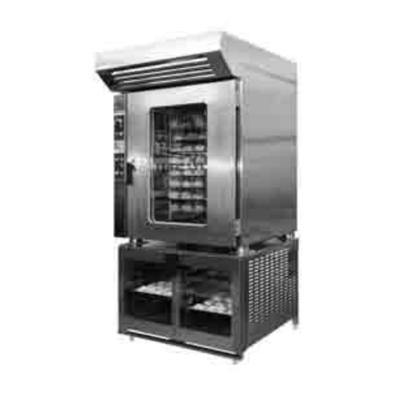
3. Functional description 3.1 Intended use of the appliance Mini Rotor 7M/10M is a convection oven intended for baking and roasting. The oven can be used as a single unit or combined with a stand or a proving cabinet. The proving cabinet has a separate manual. -
Page 10: Control Panel
1.7.2008 Rev. 1.0 Functional description 3.3 Control panel The oven functions are operated from the control panel. MAIN SWITCH YELLLOW PILOT LIGHT. Yellow pilot light is on when the rotation or fan mo- tor is overloaded. Contact the service. GREEN PILOT LIGHT. Green pilot light is on when voltage has been turned on with the main switch. -
Page 11: Time And Temperature Adjuster
1.7.2008 Rev. 1.0 Functional description TURNTABLE STOP BUTTON. When you open the oven door, push the button until the rack is in a position where the baking plates can be removed. STEAM EXHAUST VALVE. Knob is located on the exhaust hood. Turning the knob to the left will open the steam valve. -
Page 12: Operation Instructions
1.7.2008 Rev. 1.0 Operation instructions 4. Operation instructions 4.1 Before using the oven Before using the oven check the following: • Has the oven been connected to the water supply network and is it fitted with a shut-off valve. • Is the shut-off valve on the network water pipe in the open position. -
Page 13: Moistening
1.7.2008 Rev. 1.0 Operation instructions During baking the steam exhaust valve is normally closed. If there is too much steam in- side the oven, open the steam exhaust valve to remove the excessive moisture. When bak- ing products that bind a lot of water, the steam exhaust valve can be kept totally open. When baking products that require a high temperature and a short baking time, it is rec- ommended to keep the steam exhaust valve open, as oxygenous air contributes to brown- ing and improves the flavour. -
Page 14: After Use
1.7.2008 Rev. 1.0 Operation instructions 4.3 After use 4.3.1 Cleaning Use of a hose or pressure washer to clean the oven is forbidden. Before cleaning the oven, please remember that it remains hot for a long time after use. The oven cools down faster, if the door is opened. The oven is an electrical appliance. -
Page 15: Service
1.7.2008 Rev. 1.0 Operation instructions Cleaning the turntable To soak and clean the turntable, remove it first from the heating chamber. To remove the rotating rack, do the following: • Turn the turntable with your hands so that it moves to the normal position for load- ing baking plates. -
Page 16: Installation
1.7.2008 Rev. 1.0 Installation 5. Installation 5.1 General Please read these instructions carefully as they contain important information regarding installation. The installation of this appliance must be carried out in accordance with the manufactur- er’s instructions and in compliance with local rules and regulations. These instructions must be used together with the installation drawings. -
Page 17: Electricity Connection
1.7.2008 Rev. 1.0 Installation 5.4 Electricity connection To facilitate future maintenance and to increase safety, install a separate mains switch near the appliance. This switch must disconnect the appliance completely from the elec- trical supply network. After the electrical connections have been made, the rotation direction must be checked. An arrow indicates the direction of rotation of the fan motor. -
Page 18: Factory Settings
1.7.2008 Rev. 1.0 Installation Before using the oven: • check the rotation directions of fan and rotation motors. • pour some water in the drain. • make sure that water flows out of the drain water pipe. After checking, heat the oven to about 250°C and keep it at this temperature until the smell of protective grease and insulation has disappeared. - Page 19 1.7.2008 Rev. 1.0 Installation Mini Rotor 7M: Nozzle holes have been set at the factory according to the following table: Nozzle line 1 Nozzle line 2 Nozzle line 3 Fastening place A Fastening place B Fastening place C Nozzle settings (see figure below):...
- Page 20 1.7.2008 Rev. 1.0 Troubleshooting 6. Troubleshooting PROBLEM REASON WHAT TO DO Oven does not function ON/OFF key is in OFF position Press the ON/OFF key Fuse is off Call the service No light inside the heating chamber Fuse is off Call the service Bulbs burnt out Change the bulbs...
- Page 21 1.7.2008 Rev. 1.0 Technical specifications Technical specifications Main and control circuit diagram T01491A4 P1 Main and control circuit diagram T01566A4 P2 Installation drawing T00778 C3 Installation drawing T00778 D3 Installation drawing T00934 D3 Installation drawing T00934 E3...
- Page 22 Main and control circuit diagram T01491A4 P1...
- Page 23 Main and control circuit diagram T01566A4 P2...
- Page 24 Installation drawing T00778 C3...
- Page 25 Installation drawing T00778 D3...
- Page 26 Installation drawing T00934 D3...
- Page 27 Installation drawing T00934 E3...
- Page 28 Package dimensions of the oven with stand WxDxH 1118x1287x2405 mm Package dimensions of the oven with proving cabinet WxDxH 1118x1287x2235 mm Electricity connection See installation drawing Water connections See installation drawing Conditions of use Normal kitchen conditions, temperature above 0°C 7M=MINI ROTOR 7M, 10M=MINI ROTOR 10M...
Need help?
Do you have a question about the MINI ROTOR 7M and is the answer not in the manual?
Questions and answers