Table of Contents
Advertisement
Quick Links
Advertisement
Table of Contents

Subscribe to Our Youtube Channel
Related Manuals for PeakTech 4135


Summary of Contents for PeakTech 4135
- Page 1 PeakTech 4130 / 4135 / 4140 ® Operation manual Digital Spectrum Analyzer...
- Page 2 Do not touch exposed connectors and components when the unit is powered. Do not operate with suspected failures If you suspect a failure of this product, please contact PEAKTECH authorized maintenance personnel to detect. Any maintenance, adjustment or parts replacement must be performed by PEAKTECH authorized maintenance personnel.
- Page 3 to discharge static electricity before connecting cable to the instrument. Handling To avoid instrument sliping down during handling which may damage the keys, knob or interfaces and other parts on the panel, please pay attention to handling safty Safety terms and symbols Terms in this guide.
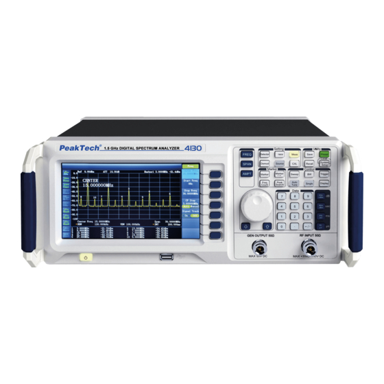
- Page 4 Brief introduction of Digital Spectrum Analyzer The PeakTech 4130 / 4135 / 4140 is a Spectrum Analyzer with compact design, easy handling, high cost – performance ratio and various functions. It has a keyboard layout which is easy to operate, high-definition color LCD screen and various remote communication interfaces.
- Page 5 Overview Abstract: Chapter 1 Getting started This chapter introduces the front and rear panels, user interface and notes for first operation of the Spectrum Analyer. Chapter 2 Front and Rear panel operation This chapter describes the functions of the keys on the front panel, and introduces menu functions of each key in detail.
- Page 6 Format specification: 1. Key: This guide usually uses “text box+text (bold)” to indicate a key on front panel, such as FREQ indicates FREQ key. 2. Menu: This guide usually uses “character shading+text (bold)” to indicate a menu, such as “center frequency” indicates the center frequency menu option under FREQ key.
-
Page 7: Table Of Contents
Content Chapter 1 Getting started Initial inspect Outlook and dimension Prepare for use Front panel Function keys on front panel Rear panel Parameter setting Chapter 2 Basic operation 1. Basic Settings Center Frequency Start Freq Stop Freq CF Step Signal Track 2. - Page 8 Math All Clear Marker Measurement Marker Select Normal Delta Delta Pair Span Pair Mark Trace Readout Marker Fctn Select Marker Noise Marker N dB BW Marker Table Freq Count 8. Peak Search Next Peak Peak Right Peak Left Peak Min Peak P-P Cont Peak Peak Para...
- Page 9 Channel Power (CP) Adjacent Channel Power (ACP) Ocuupied Bandwidth (OBW) Chapter 3 Remote control Chapter 4 Specifications Frequency Amplitude Sweep Trigger Trakcing source Input/output General characteristics Chapter 5 Appendix Standard accessories Optional accessories Options...
-
Page 10: Chapter 1 Getting Started
Chapter 1 Getting started This chapter introduces the front and rear panels, user interface and notes for first operation of the Spectrum Analyer. The contents of this chapter are as follows: Initial inspect Outlook and dimensions Front panel ... -
Page 11: Initial Inspect
3. Check the accessories Check the accessories according to the packing list, if damaged or missing, please contact your PeakTech distributor. Outlook and dimension Spectrum Analyzer 9kHz-3.0GHz Setting... -
Page 12: Prepare For Use
Prepare for use Adjust the legs of the instrument Open the legs of the Analyzer as bracket of the instrument to make it tilted upward before operation, which makes the following operation and observation more convenient. When the instrument is not in use, the user can close the support legs to facilitate placement or removal. - Page 13 Table 1-2 Description of function keys on front panel Function Function description Set informations like center frequency, start frequency and FREQ end frequency etc. Set the frequency range of sweep. SPAN Set parameters like reference level, RF attenuator, scale, Y- AMPT axis units etc.
- Page 14 Config demodulation function Demod Select and control measurement function Meas Set tracking source Source Set information about the auto calibration of the instrument . Set parameters of trace. Trace Set detection mode of detector. Detector Set parmaters of system. System Setup Set information about trigger.
-
Page 15: Rear Panel
Rear panel RS232 Trigger in 10MHz IN/OUT REPLACE FUSE USB Device AS SPECIFIED DISCONNECT POWER CORD BEFORE REPLACING FUSE 100-240V AC 50/60Hz T 3A/250V SHIJIAZHUANG SUIN INSTRUMENTS CO.,LTD. 1. VGA port This port provides VGA vedio signal output, connect this interface with VGA cable 2. -
Page 16: Parameter Setting
Parameter setting Realize parameter input with numeric keys, adjusting knob or direction keys. This section introducs thress parameter setting methods with an example (set center frequency to 1500 MHz). 1. Use numeric keys 1) Press FREQ Center frequency; 2) Use numeric keys to input value “750”; 3) Select desired unit “MHz”... -
Page 17: Chapter 2 Basic Operation
Chapter 2 Basic operation The contents of this chapter are as follows: Basic Settings Sweep and Functions Settings Measurement Settings The using and function settings of Marker Shortcut System Settings... -
Page 18: Basic Settings
Basic Settings FREQ Set the frequency parameter of analyzer. The analyzer sweeps within a specified range, and the sweep will start once you change this parameter. The frequency range of current channel can be expressed by either of two ), or center groups of paramenters: Start Frequency/Stop Frequency(f start stop... -
Page 19: Stop Freq
Parameter Description Default 0 GHz Range 0 Hz ~ 1.5GHz (P4130) 0 Hz ~ 2.2GHz (P4135) 0 Hz ~ 3.0GHz (P4140) Unit GHz, MHz, kHz, Hz Knob Step Span>0, step=span/200 Span=0, step=RBW/100, Min=1 Hz Arrow Keys Step CF step Stop Freq Set the stop frequency of current channel, displays at the right scale. -
Page 20: Signal Track
Parameter Description Default 150MHz (P4130), 220MHz (P4135), 300MHz (P4140) Range 1 Hz ~ 3.0GHz (P4140); 2.2GHz (P4135) ; 1.5GHz (P4130) Unit GHz, MHz, kHz, Hz Knob Step Span>0, step=span/200 Span=0, step=VBW/100, Min=1 Hz Arrow Keys Step In 1-2-5 sequency Signal Track Enable or disable the function of signal track. -
Page 21: Full Span
Span Set the frequency range of current channel. When pressed, the frequency mode is switched to Center Freq/Span for input, and the Center Freq and Span are shown at the lower left and right of the display grid. Key points: The Start/Stop Frequency varies with the changing of Span automatically. -
Page 22: Auto Scale
Auto Scale To set the highest resolution for Y axis of current screen on condition that the signal is full displayed. A reference level is set automatically and ensures the peak of signal always on the topmost of grid for best view of tracing line. Figure 2-2 Before Auto Scale Figure 2-3 After Auto Scale Ref Level... -
Page 23: Scale/Div
Key points: When preamplify is on, up limit for input attenuation can set to be 30dB. You can adjust reference level to ensure above formula 2-3. You can modify this parameter by numeric keys, knob and arrow keys. For more details, please refer to “Parameter Input”. -
Page 24: Auto Range
Assign an offset to the reference level to compensate for gains or losses generated between the measured device and the analyzer. Then the level of external amplitude tansformer input can be taken as reference for measured signal level. Key points: ... -
Page 25: Int Preamp
Int Preamp Turn on or off the preamplifier located at front of RF. When the function enabled, the preamplifier will reduce the display average noise level in order to distinguish the small signal among noises. Key points: The icon will be displayed on the left screen when the preamplifier is on. Max Mix Level Set max input level of mixer according to the manaitude of signal. -
Page 26: Rbw
Sweep and Function Settings Set the parameters of RBW (Resolution Bandwidth), VBW (Video Bandwidth) and Dectector. Set the RBW (Resolution Bandwidth) in order to distinguish two close signals. Key points: Reducing the RBW to get higher frequency resolution, but will cause the longer sweep (In Auto Sweep mode, sweep time will be affected both by RBW and VBW). -
Page 27: Detector Type
Parameter Description Default Range 0.000001 ~ 100000 Unit Knob Step In 1-3-10 sequence Arrow Keys Step In 1-3-10 sequence Detector Set the detector type of analyzer for different signal measurement. Detector Type While displaying a wider span, analyzer always capture the whole data for each pixel whthin a specified time. -
Page 28: Sweep
Where, VRMS denotes the mean square root value of voltage, unit is V. N denotes the number of smples assigned for each pixel. vi denotes the envelop of the samples, unit is V. Reference Resistance R can be used for Power calculation: 6. -
Page 29: Single
Key points: In single mode, when pressed, the system enter into continue sweep mode and will sweep when trigger condition allows. In continue mode, the system send initialization signal automatically and enter into the judement program directly when each sweep finishes. Single In single sweep mode, the menu is used for the initialization of trigger. -
Page 30: Trigger Type
Parameter Description Default Range 1 ~ 9999 Unit Knob Step Arrow Keys Step Trigger Set the parameters of trigger function. Trig Type The trigger type includes Free Run, Video and External. Each icon of selected type will be shown at the left of screen. 1. -
Page 31: Trace Type
memory and recall when needed. User can press “Save” key to store the data, detail method is descriped in “Save”. Trace Type Set the type of the current trace or disable it. The system calculates the sample data with a specific operation according to the slected trace type and finally displays the result. -
Page 32: Math
Math 1. Function Set the computational method of the math trace. A-B: subtract Trace B from Trace A. A+Constant: add a constant to Trace A. A-Constant: subtract a constant from Trace A. 2. A Assign a value to A from Trace 1, Trace2 or Trace 3. The default is Trace 1 (“T1”). 3. -
Page 33: Marker Measurement
Marker Measurement Marker The marker shows as a rhombic sign for marking the trace point. Easy for user to readout the amplitude, frequency and sweep time of each point through marker. Key points: Screen can show 4 pairs of marker at most, but only one pair or one single marker is active every time. -
Page 34: Delta Pair
Key points: If there is active marker, pressing this key will enalble a reference marker at the place of current marker. Or else both the reference marker and Delta Marker will be activated together at the position of center frequency. ... -
Page 35: Mark Trace
Marker Trace Select one trace for current marker from 1, 2, 3 Math and Auto (default). When select Auto, the system will search desired trace in the order of “Clear Write”, “Max Hold”, “Min Hold”, “Video Avg”, “Power Avg” and “Freeze”. If search more than two traces as result, it will be selected in sequence of trace number 1, 2, 3 accordingly. -
Page 36: N Db Bw
N dB BW Enable the function of N dB bandwidth measurement or se the value of N dB. The N dB denotes the frequency difference points that are located on both sides of the current marker while the amplitude falls off (N<0) or rises (N>0) N dB sperately, see below figure 2-8: Figure 2-8 Key points:... -
Page 37: Freq Count
Figure 2-9 All Off Turn off all the markers and related functions. Freq Count Frequency counter reading Figure 2-10 1. On/Off Turn on or off the frequency counter. Key points: If no active marker selected, turing on the frequency counter will open a Normal marker automatically. -
Page 38: Peak Search
Peak Search Open the Peak searching menu and execute the searching function. Key points: If select Max in option of Peak Search, it will search the maximum on trace and mark it. If select Param in option of Peak Search, it will search and mark the peak that meets the condition of the parameter. -
Page 39: Peak Table
Table 2-24 Peak Excursion Parameter Description Default 10 dB Range 0 dB ~ 200 dB Unit Knob Step 1 dB Arrow Keys Step 1 dB 2. Peak Threshold Specify the minimum amplitude of peak, only peaks whose amplitude beyong the limit can be treated as desired peak. -
Page 40: Marker
Marker-> Set the other system parameters (such as frequency, Reference level) using the current marker reading. Press Marker -> to enable a marker if none of them are active at present. Mkr->CF Set the center frequency of analyzer to be the frequency of current marker. ... -
Page 41: Auto Tune
Shortcut Auto Tune Search for signals antomatically throughout the whole range and adjust the frequency and amplitude to their best status and realize one-key signal search and auto setting of parameters. Figure 2-11 Befor the Auto Tune Figure 2-12 After the Auto Tune Key Points: ... -
Page 42: Active Fctn
Active Fctn Select the position in which the active function is displayed for convenient view of the trace. Optional is Top, Center, Bottom, the default is Top. Screen Off Turn on or off the display, the default is On. Preset When this key pressed, the system will return to Factory settings or user defined state. -
Page 43: System Setup
System Setup System Setup Set the parameters on system. Language Select Chines or English for display language. Reset The function includes: select the instrument setting (Last or Preset) to be recalled after the analyzer is powered on. Set the type for Preset (“Factory Setting” or User Defined). -
Page 44: Meas
Meas The analyzer provides advanced measurement function including Channel Power, Adjacent Channel Power and Occupied Bandwidth. Channel Power Channel Power Measures the total power of signal within the specified channel bandwidth, which includes the Channel Power and Power Density. Channel power: the power within the integral bandwidth Power Density:... -
Page 45: Ocuupied Bandwidth (Obw)
Pos Limits: sets the threshold parameters for right adjacent channels En: opens or closes the adjacent channels from one to six channels Meas Type selects measurements type as Total Pwr Ref or PSD Ref. Default is Total Pwr Ref. Total Pwr Ref sets total power reference to be Manual or Auto Auto the total power reference is set automatically... -
Page 46: Chapter 3 Remote Control
Chapter 3 Remote control Users can control this series of digital Spectrum Analyzers through USB, LAN and RS- 232 remote interface. This chapter introduces the basic information and method of remote control of the instrument. The contents of this chapter are as follows: ... -
Page 47: Chapter 4 Specifications
Chapter 4 Specifications Warm up for 30 minutes before operation. The instrument is within calibration period and self-calibration has been done. -
Page 48: Frequency
Specifications 1. Frequency 1.1 Frequency Range Range P 4130 9kHz to 1.5GHz P 4135 9kHz to 2.2GHz P 4140 9kHz to 3.0GHz Resolution 1.2 Internal reference frequency Reference frequency 10MHz Aging rate <5×10 /year (20 ℃ to 30 ℃) Teperature stability <5×10... -
Page 49: Amplitude
2. Amplitude 2.1 Measurement range Range P 4130 10MHz to 1.5GHz DANL to +30 dBm P 4135 10MHz to 2.2GHz DANL to +30 dBm P 4140 10MHz to 3.0GHz DANL to +30 dBm 2.2 Maximum input level DC voltage Continuous wave RF power +30dBm (1.0 W) -
Page 50: Sweep
2.7 Resolution bandwidth switch Uncertainty 100Hz to 1MHz, relative to RBW 1kHz ±0.15dB 2.8 Reference level Range -100dBm to +30dBm, step is 1dB Resolution logarithm scale 0.01dB Linear scale 4 digits 2.9 Full-amplitude precision Full-amplitude precision 95% confedence level, S/N>20dB, RBW=VBW=1 kHz, pre-amplifier is closed, 10dB attenuation, -10dBm<reference level<0, 10MHz<fc<3.0GHz, within 20 ℃... -
Page 51: Trakcing Source
5. Tracking Generator 5.1 Tracking source Frequency range 9kHz to 1.5GHz (P4130) 9kHz to 2.2GHz (P4135) 9kHz to 3.0GHz (P4140) Output power -20dBm to 0dBm, step is 1dB Output flatness 20MHz to 2.7GHz ±3dB 20MHz to 2.2GHz ±2dB 20MHz to 1.5GHz ±2dB 6. -
Page 52: Chapter 5 Appendix
We herewith confirm, that the units are calibrated by the factory according to the specifications as per the technical specifications. We recommend to calibrate the unit again, after one year. © PeakTech® 10/2014/Ehr PeakTech Prüf- und Messtechnik GmbH - Kornkamp 32 - DE-22926 Ahrensburg / Germany +49-(0) 4102-42343/44 +49-(0) 4102-434 16 ...
Need help?
Do you have a question about the 4135 and is the answer not in the manual?
Questions and answers