Advertisement
Quick Links
Advertisement

Related Manuals for Sentiotec LAVA


Summary of Contents for Sentiotec LAVA
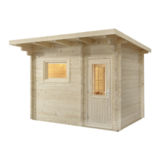
- Page 1 Assembly Instruction LAVA Garden sauna 375 x 319 x 270 cm Version 10/17...
- Page 2 Assembly instructions Garden sauna LAVA Exterior dimension: 375 x 319 x 270 cm Interior dimension: 200 x 200 x 210 cm 200 x 104 x ~260 cm Wall thickness: 70 mm Dear customer, Before you begin with the work, check that all the individual parts have been delivered against the parts list.
- Page 3 LAVA parts list Front face with doors 2 weather boards 317.5 x 13.5 x 2 cm 1 block plank 341 x 7 x 7 cm 2 roof support slats 200 x 4 x 4 cm with recess for door 2 roof support slats 192 x 4 x 4 cm 3 block planks 341 x 14.6 x 7 cm...
- Page 4 Assembly instructions LAVA GARDEN SAUNA Notes for the planning permission, foundation, anchorage, delivery and unloading Planning permission Before installing the garden sauna, make sure you enquire about whether planning permission is required at your local planning authority (municipal office, magistrate).
- Page 5 However, the two options below have proven to be the best in practice: • Foundation slab (base plate) • Strip foundation For both types, a foundation that is absolutely flat and load-bearing must be ensured. Only then can the assembly of the individual modules be ensured without difficulties and with a precise fit. Once the concrete slab has been completed and dried out, we recommend torching it with roofing felt or torch-on felt in order to seal it completely.
- Page 6 Assembly instructions Strip foundation Depending on the structural requirements and local conditions, strip foundations can be laid in different ways. There are two types of strip foundations: • strip foundation - not reinforced • strip foundation - reinforced To make a frost-proof strip foundation, you must dig at least 80 cm deep into the ground. The supporting walls of the garden sauna are then laid on the foundation strips.
- Page 7 Note: The foundations must be absolutely flat to ensure the load-bearing capacity of the sauna. If the foundation slab is larger than the floor space of the garden sauna, rainwater can start to collect around the garden sauna. This means that the wooden wall elements would be constantly standing on wet ground.
- Page 8 Assembly instructions Base frame for outer sauna Screws 5 x 100 mm Fig. 1.1 Screws 5 x 100 mm Fig. 1.2 Fig. 1.3...
- Page 9 1 block plank 230 x 14.6 x 7 cm with door recess Fig. 1.4 1 block plank 341 x 7 x 7 cm with door recess 1 block plank 341 x 14.6 x 7 cm with ventilation recess Fig. 1.5...
- Page 10 Assembly instructions Fig. 1.6 Fig. 1.7...
- Page 11 Fig. 1.8 Fig. 1.9...
- Page 12 Assembly instructions Threaded rods Screw joints at top Fig.1.10 Threaded rods Screw joints at bottom Fig. 1.11 Ventilation shutter 4 screws 3 x 40 mm Fig. 1.12...
- Page 13 Fig. 1.13 Floor - screws 3.5 x 50 mm Screws 5 x 100 mm Fig. 1.14 Skirting board - screws 3.2 x 40 mm...
- Page 14 Assembly instructions Measure from the floor to the upper edge of the roof support slat 206 cm. Screws 4 x 70 mm 206 cm Fig. 1.15 Screw the roof elements from above with the support slats Screws 5 x 80 mm Fig.
- Page 15 Fig. 1.18 Fig. 1.19...
- Page 16 Assembly instructions Fig. 1.20 Fig. 1.21...
- Page 17 Fig. 1.22 Place the door element in the doorway from the inside, take the top slat (1), place it so that left and right is the same and screw the slat to the window from the outside. Next, screw on the side mount- ing slats.
- Page 18 Assembly instructions Screws 5 x 70 mm 87 cm 41 cm Fig. 1.25 Fig. 1.26...
- Page 19 Screws 3.5 x 50 mm Bench screen - view from rear Fig. 1.27 Bench screen Fig. 1.28...
- Page 20 Assembly instructions Screws 3.5 x 50 mm 25 cm Fig. 1.29 4 screws 3 x 40 mm Fig. 1.30 Fig. 1.31 Fig. 1.32...
- Page 21 Screws 3 x 40 mm Fig. 1.33 Fig. 1.34...
- Page 22 Assembly instructions First, put the mounting slats of the door and the screws in the cabin. Then place the door element in the doorway, take the top slat (1), place it so that left and right is the same and screw the slat to the door. Next, screw on the side mounting slats.
- Page 23 Screws 3.5 x 50 mm 2 cm Fig. 1.88 Fig. 1.37 Weather board, side, screws 3.5 x 50 mm Fig.1.39...
- Page 24 Assembly instructions Lay the roofing felt so that it overlaps and attach it with the roofing felt nails provided. Start laying it at the bottom end of the roof. Fig. 1.40 Fig. 1.41...
- Page 25 LAVA FLOOR PLAN 375 x 319 x 270 cm 3190 2300 2000 Glastür 1915x590x8mm 2140 LAVA 230x341x270 Grundriss Komm. Auftr. Nr.: Datum 16.03.2015...
- Page 26 GmbH | Division of Harvia Group | Oberregauer Straße 48, A-4844 Regau T +43 (0) 7672/277 20-567 | F -801 | info@sentiotec.com | www.sentiotec.com...
Need help?
Do you have a question about the LAVA and is the answer not in the manual?
Questions and answers