Endress+Hauser Proline Promag 55 Operating Instructions Manual
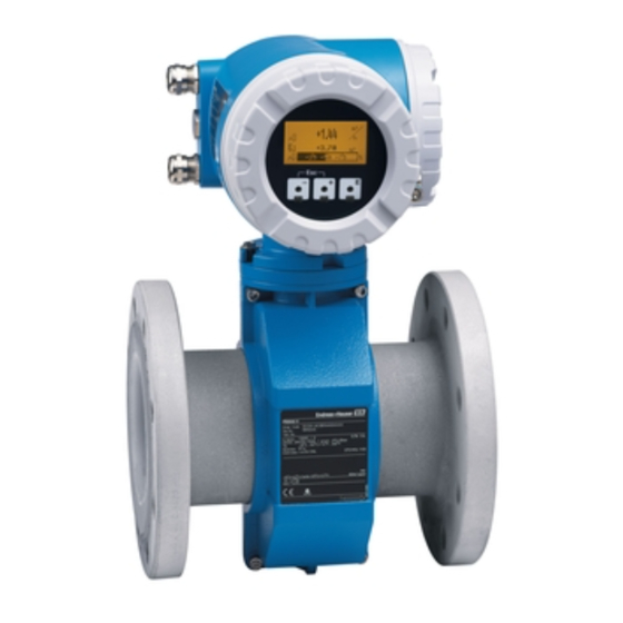
Foundation fieldbus
electromagnetic flow measuring system
Hide thumbs
Also See for Proline Promag 55:
- Operating instructions manual (162 pages) ,
- Operating manual (130 pages) ,
- Installation instruction (16 pages)

Subscribe to Our Youtube Channel
Related Manuals for Endress+Hauser Proline Promag 55


Summary of Contents for Endress+Hauser Proline Promag 55
-
Page 1: Operating Instructions
Operating Instructions Proline Promag 55 FOUNDATION Fieldbus Electromagnetic Flow Measuring System BA126D/06/EN/07.09 71089883 Valid as of version: V 3.00.XX (device software) -
Page 3: Table Of Contents
Proline Promag 55 FOUNDATION Fieldbus Table of contents Table of contents Safety instructions ....5 4.4.2 Fieldbus connector ....46 4.4.3 Terminal assignment . - Page 4 Proline Promag 55 FOUNDATION Fieldbus Table of contents Accessories specific to measuring principle ..79 Communication-specific accessories ... . 80 Service-specific accessories ....80 Troubleshooting .
-
Page 5: Safety Instructions
• The device must be operated only by persons authorized and trained by the system operator. Strict compliance with the instructions in the Operating Instructions is mandatory. • Endress+Hauser is willing to assist in clarifying the chemical resistance properties of parts wetted by special fluids, including fluids used for cleaning. However, small changes in temperature, concentration or the degree of contamination in the process can result in changes to the chemical resistance properties. -
Page 6: Return
In the event of elevated fluid temperatures, please ensure that fire protection is in place. • The manufacturer reserves the right to modify technical data without prior notice. Your Endress+Hauser distributor will supply you with current information and updates to these Operating Instructions. Return •... -
Page 7: Identification
Proline Promag 55 FOUNDATION Fieldbus Identification Identification Device designation The flow measuring system consists of the following components: • Promag 55 transmitter • Promag S and Promag H sensors Two versions are available: • Compact version: transmitter and sensor form a single mechanical unit. -
Page 8: Nameplate Of The Sensor
Identification Proline Promag 55 FOUNDATION Fieldbus 2.1.2 Nameplate of the sensor PROMAG S 55S1H-XXXXXXXXXXXX Order Code: 12345678901 Ser.No.: ABCDEFGHJKLMNPQRST TAG No.: 1.0000/0000 0.2% CAL K-factor: DN100 DIN EN PN40 –20 °C ...+150°C/–4 ...+300°F °F Materials: 1.4435/316L EPD/MSÜ, R/B Electrodes: –20°C (–4°F)<Tamb<+50°C (+122°F) -
Page 9: Nameplate For Connections
Proline Promag 55 FOUNDATION Fieldbus Identification 2.1.3 Nameplate for connections active See operating manual passive Betriebsanleitung beachten normally open contact Observer manuel d'instruction normally closed contact 12345678912 Ser.No.: L1/L+ Supply / Versorgung / N/L- Tension d'alimentation 26= FF + FOUNDATION Fieldbus... -
Page 10: Certificates And Approvals
EMC requirements of IEC/EN 61326. The measuring system described in these Operating Instructions therefore complies with the legal requirements of the EU Directives. Endress+Hauser confirms this by affixing the CE mark to it and by issuing the CE Declaration of Conformity. -
Page 11: Installation
Proline Promag 55 FOUNDATION Fieldbus Installation Installation Incoming acceptance, transport and storage 3.1.1 Incoming acceptance On receipt of the goods, check the following points: • Check the packaging and the contents for damage. • Check the shipment, make sure nothing is missing and that the scope of supply matches your order. -
Page 12: Storage
Installation Proline Promag 55 FOUNDATION Fieldbus Transporting flanged devices DN > 300 (12") Use only the metal eyes on the flanges for transporting the device, lifting it and positioning the sensor in the piping. " Caution! Do not attempt to lift the sensor with the tines of a fork-lift truck beneath the metal casing. This would buckle the casing and damage the internal magnetic coils. -
Page 13: Installation Conditions
Proline Promag 55 FOUNDATION Fieldbus Installation Installation conditions 3.2.1 Dimensions All the dimensions and lengths of the sensor and transmitter are provided in the separate documentation "Technical Information". 3.2.2 Mounting location The accumulation of air or gas bubbles in the measuring tube could result in an increase in measuring errors. - Page 14 Installation Proline Promag 55 FOUNDATION Fieldbus Partially filled pipes Partially filled pipes with gradients necessitate a drain-type configuration. The Empty Pipe Detection function offers additional protection by detecting empty or partially filled pipes → ä 75. " Caution! Risk of solids accumulating. Do not install the sensor at the lowest point in the drain. It is advisable to install a cleaning valve.
-
Page 15: Orientation
Proline Promag 55 FOUNDATION Fieldbus Installation 3.2.3 Orientation An optimum orientation position helps avoid gas and air accumulations and deposits in the measuring tube. Promag, nevertheless, supplies a range of functions and accessories for correct measuring of problematic fluids: • Electrode Cleaning Circuitry (ECC) to prevent electrically conductive deposits in the measuring tube, e.g. -
Page 16: Inlet And Outlet Runs
Installation Proline Promag 55 FOUNDATION Fieldbus 3.2.4 Inlet and outlet runs If possible, install the sensor in a location upstream of fittings such as valves, T-pieces, elbows, etc. Compliance with the following requirements for the inlet and outlet runs is necessary in order to ensure measuring accuracy. -
Page 17: Foundations, Supports
Proline Promag 55 FOUNDATION Fieldbus Installation 3.2.6 Foundations, supports If the nominal diameter is DN ≥ 350 (14"), mount the sensor on a foundation of adequate load- bearing strength. " Caution! Risk of damage. Do not support the weight of the sensor on the metal casing: the casing would buckle and damage the internal magnetic coils. -
Page 18: Nominal Diameter And Flow Rate
Installation Proline Promag 55 FOUNDATION Fieldbus 3.2.8 Nominal diameter and flow rate The diameter of the pipe and the flow rate determine the nominal diameter of the sensor. The optimum flow velocity is between 2 and 3 m/s (6 to 10 ft/s). The flow velocity (v), moreover, has to be matched to the physical properties of the fluid: •... - Page 19 Proline Promag 55 FOUNDATION Fieldbus Installation Flow characteristic values for Promag S sensor (US units) Nominal Recommended flow rate Factory settings diameter Min./max. full scale value Low flow cut off (v ≈ 1.0 or 33 ft/s) (v ≈ 0.1 ft/s) [inch] ½"...
- Page 20 Installation Proline Promag 55 FOUNDATION Fieldbus Flow characteristic values for Promag H sensor (SI units) Nominal Recommended flow rate Factory settings diameter Min./max. full scale value Full scale value Pulse value Low flow cut off (v ≈ 0.3 or 10 m/s) (v ≈...
-
Page 21: Length Of Connecting Cable
Proline Promag 55 FOUNDATION Fieldbus Installation 3.2.9 Length of connecting cable In order to ensure measuring accuracy, please comply with the following instructions when installing the remote version: • Secure the cable run or route the cable in an armored conduit. Movement of the cable can falsify the measuring signal, particularly if the fluid conductivity is low. -
Page 22: Installation
Ground cable (DN 15 to 600 / ½ to 24") Ground cables are optionally available in different versions from Endress+Hauser: • Ground cable preinstalled at the flange → Order option (see price list) • Ground cable (not pre-installed) as an accessory → ä 79 Detailed assembly instructions →... - Page 23 Proline Promag 55 FOUNDATION Fieldbus Installation Screw tightening torques Note the following points: • The tightening torques listed below are for lubricated threads only. • Always tighten the screws uniformly and in diagonally opposite sequence. • Overtightening the screws will deform the sealing faces or damage the seals.
- Page 24 Installation Proline Promag 55 FOUNDATION Fieldbus Promag S EN (DIN) Screws Max. tightening torque [Nm] Nominal Pressure diameter rating [mm] [bar] Natural Polyurethane PTFE Hard rubber rubber PN 25 20 × M 33 – – PN 10 20 × M 27 –...
- Page 25 Proline Promag 55 FOUNDATION Fieldbus Installation Promag S Screws Max. tightening torque [Nm] Nominal Pressure diameter rating [mm] Natural Polyurethane PTFE Hard rubber rubber 4 × M 12 – – – – 4 × M 12 – – – –...
- Page 26 Installation Proline Promag 55 FOUNDATION Fieldbus Sensor AS 2129 Screws Max. tightening torque [Nm] Nominal diameter Pressure rating [mm] PTFE Natural rubber Table E 4 × M 12 – Table E 4 × M 16 – Table E 4 × M 16 –...
- Page 27 Proline Promag 55 FOUNDATION Fieldbus Installation Installing the high-temperature version (with PFA lining) The high-temperature version has a housing support for the thermal separation of sensor and transmitter. The high-temperature version is always used for applications in which high ambient temperatures are encountered in conjunction with high fluid temperatures.
-
Page 28: Installing The Promag H Sensor
• The sensor might require support or additional attachments, depending on the application and the length of the piping run. When plastic process connections are used, the sensor must be additionally supported mechanically. A wall-mounting kit can be ordered separately from Endress+Hauser as an accessory → ä 79. a0004301 Fig. 20: Promag H process connections (DN 2 to 25 /1/12 to 1", DN 40 to 100 / 1½... - Page 29 • Ground rings can be ordered separately from Endress+Hauser as accessories → ä 79. When placing the order, make certain that the ground ring is compatible with the material used for the electrodes.
- Page 30 Tack-weld the Promag H sensor into the pipe. A suitable welding jig can be ordered separately from Endress+Hauser as an accessory → ä 79. Remove the threaded fasteners from the process-connection flange. Remove the sensor complete with seal from the pipe.
-
Page 31: Turning The Transmitter Housing
Proline Promag 55 FOUNDATION Fieldbus Installation 3.3.3 Turning the transmitter housing Turning the aluminum field housing Warning! The turning mechanism in devices with Ex d/de or FM/CSA Cl. I Div. 1 classification is not the same as that described here. The procedure for turning these housings is described in the Ex-specific documentation. -
Page 32: Turning The Local Display
Installation Proline Promag 55 FOUNDATION Fieldbus 3.3.4 Turning the local display Unscrew the electronics compartment cover from the transmitter housing. Press the latches on the side of the display module and pull the module out of the electronics compartment cover. -
Page 33: Installing The Wall-Mount Housing
Proline Promag 55 FOUNDATION Fieldbus Installation 3.3.5 Installing the wall-mount housing There are various ways of installing the wall-mount housing: • Mounted directly on the wall • Panel mounting (with separate mounting kit, accessories) → ä 34 • Pipe mounting (with separate mounting kit, accessories) → ä 34 "... -
Page 34: Endress+Hauser
Installation Proline Promag 55 FOUNDATION Fieldbus Panel mounting Prepare the opening in the panel as illustrated. Slide the housing into the opening in the panel from the front. Screw the fasteners onto the wall-mount housing. Place the threaded rods in the fasteners and screw them down until the housing is seated tightly against the panel wall. -
Page 35: Post-Installation Check
Proline Promag 55 FOUNDATION Fieldbus Installation Post-installation check Perform the following checks after installing the measuring device in the pipe: Device condition/specifications Notes Is the device damaged (visual inspection)? → ä 99 Does the device correspond to specifications at the measuring point, including process temperature and pressure, ambient temperature, minimum fluid conductivity, measuring range, etc.? -
Page 36: Wiring
• When connecting Ex-certified devices, please take note of the instructions and wiring diagrams in the Ex-specific supplement to these Operating Instructions. Should you have any questions, please contact your Endress+Hauser sales office for assistance. • When installing remote versions, please make sure that the serial number on the sensor and the serial number on the transmitter are identical. -
Page 37: Maximum Overall Cable Length
Proline Promag 55 FOUNDATION Fieldbus Wiring Suitable fieldbus cables (Type A) from various manufacturers for non-hazardous areas are listed below: • Siemens: 6XV1 830-5BH10 • Belden: 3076F • Kerpen: CeL-PE/OSCR/PVC/FRLA FB-02YS(ST)YFL 4.1.2 Maximum overall cable length The maximum network expansion depends on the type of protection and the cable specifications. -
Page 38: Bus Termination
Wiring Proline Promag 55 FOUNDATION Fieldbus 4.1.6 Bus termination The start and end of each fieldbus segment are always to be terminated with a bus terminator. With various junction boxes (non-Ex), the bus termination can be activated via a switch. If this is not the case, a separate bus terminator must be installed. -
Page 39: Connecting The Remote Version
Proline Promag 55 FOUNDATION Fieldbus Wiring Connecting the remote version Warning! • Risk of electric shock. Switch off the power supply before opening the device. Do not install or wire the device while it is connected to the power supply. Failure to comply with this precaution can result in irreparable damage to the electronics. -
Page 40: Endress+Hauser
Wiring Proline Promag 55 FOUNDATION Fieldbus 4 37 36 42 41 n.c. n.c. n.c. 4 37 42 41 a0011722 Fig. 28: Connecting the remote version of the Promag S Connection compartment, wall-mount housing Connection housing, sensor Signal cable Coil current cable n.c. -
Page 41: Endress+Hauser
Proline Promag 55 FOUNDATION Fieldbus Wiring Cable termination in remote version Promag S Terminate the signal and coil current cables as shown in the figure below (Detail A). Fit the fine-wire cores with wire end ferrules (Detail B). " Caution! When fitting the connectors, pay attention to the following points: •... -
Page 42: Endress+Hauser
Wiring Proline Promag 55 FOUNDATION Fieldbus Cable termination in remote version Promag H Terminate the signal and coil current cables as shown in the figure below (Detail A). Fit the fine-wire cores with wire end ferrules (detail B: m = ferrules red, Ø 1.0 mm; n = ferrule white, Ø 0.5 mm) "... -
Page 43: Cable Specifications
Core reinforcement Cable shield Outer jacket As an option, Endress+Hauser can also deliver reinforced connecting cables with an additional reinforcing metal braid. We recommend such cables for the following cases: • Cables laid directly into the ground • Rodent damage to cables •... -
Page 44: Connecting The Measuring Unit
Wiring Proline Promag 55 FOUNDATION Fieldbus Connecting the measuring unit Field instruments can be connected to the FOUNDATION Fieldbus in two ways: • Connection via conventional cable gland → ä 44 • Connection using prefabricated fieldbus connector (option) → ä 46 4.4.1... -
Page 45: Endress+Hauser
Proline Promag 55 FOUNDATION Fieldbus Wiring N (L–) FF + L1 (L+) FF – FF – FF + 20 21 22 23 24 25 26 27 N (L-) L1 (L+) a0006388 Fig. 31: Connecting the transmitter, cable cross-section: max. 2.5 mm... -
Page 46: Fieldbus Connector
4-channel or 8-channel distribution modules. The device can therefore be supplied with the option of a ready-mounted fieldbus connector. Fieldbus connectors for retrofitting can be ordered from Endress+Hauser as a spare part → ä 79. 26.5 mm (1.040") -
Page 47: Terminal Assignment
Proline Promag 55 FOUNDATION Fieldbus Wiring 4.4.3 Terminal assignment Note! The electrical characteristic quantities are listed in the "Technical data" section. Terminal No. (inputs / outputs) Order version 20 (+) / 21 (–) 22 (+) / 23 (–) 24 (+) / 25 (–) 26 = FF + 27 = FF –... -
Page 48: Potential Equalization
Caution! When using process connections made of plastic, potential equalization must be guaranteed through the use of grounding rings → ä 28. The necessary grounding rings may be ordered separately as an accessory from Endress+Hauser (→ ä 79). 4.5.3 Connection examples for potential equalization... - Page 49 A0011893 The ground cable for flange-to-flange connections can be Fig. 34: Via the transmitter's ground terminal ordered separately as an accessory from Endress+Hauser. and the pipe flanges Version with pre-installed ground cable for DN ≤ 300 (12") (order option) Ground cables (copper wire, min. 6 mm² (0.0093 in...
-
Page 50: Degree Of Protection
Wiring Proline Promag 55 FOUNDATION Fieldbus Operating conditions Potential equalization When using the measuring device in: • pipes with cathodic protection The device is installed in the pipeline in such a way that it is potential-free. Using a ground cable (copper wire, min. 6 mm² (0.0093 in only the two pipe flanges are connected. -
Page 51: Post-Connection Check
Proline Promag 55 FOUNDATION Fieldbus Wiring Post-connection check Perform the following checks after completing electrical installation of the measuring device: Device condition and specifications Notes Are cables or the device damaged (visual inspection)? Electrical connection Notes FOUNDATION Fieldbus→ ä 36 Do the cables comply with the specification? Sensor cable →... -
Page 52: Operation
Operation Proline Promag 55 FOUNDATION Fieldbus Operation Quick operation guide The user has a number of options for configuring and commissioning the device: Local display (option) → ä 53 The local display enables you to read all important variables directly at the measuring point, configure device-specific parameters in the field and perform commissioning. -
Page 53: Local Display
Proline Promag 55 FOUNDATION Fieldbus Operation Local display 5.2.1 Display and operating elements The local display enables you to read important parameters directly at the measuring point or to configure your device using the "Quick Setup" or the function matrix. -
Page 54: Display (Operating Mode)
Operation Proline Promag 55 FOUNDATION Fieldbus 5.2.2 Display (operating mode) The display area consists of three lines in all; this is where measured values are displayed, and/or status variables (direction of flow, bar graph, etc.). You can change the assignment of display lines to variables at will in order to customize the display to suit your needs and preferences (→... -
Page 55: Icons
Proline Promag 55 FOUNDATION Fieldbus Operation 5.2.3 Icons The icons which appear in the field on the left make it easier to read and recognize measured variables, device status, and error messages. Icon Meaning Icon Meaning System error Process error... -
Page 56: Brief Operating Instructions For The Function Matrix
Operation Proline Promag 55 FOUNDATION Fieldbus Brief Operating Instructions for the function matrix Note! • See the general notes → ä 57 • Function descriptions → See the "Description of Device Functions" manual HOME position → F → Enter the function matrix O / S →... -
Page 57: General Notes
• If programming is disabled and the O/S keys are pressed in any function, a prompt for the code automatically appears on the display. • If "0" is entered as the customer’s code, programming is always enabled. • The Endress+Hauser service organization can be of assistance if you mislay your personal code. " Caution! •... -
Page 58: Error Messages
Operation Proline Promag 55 FOUNDATION Fieldbus Error messages 5.4.1 Type of error Errors which occur during commissioning or measuring operation are displayed immediately. If two or more system or process errors occur, the error with the highest priority is the one shown on the display. -
Page 59: Operating Programs
5.5.1 "FieldCare" operating program FieldCare is Endress+Hauser’s FDT-based plant asset management tool and enables the configuration and diagnosis of intelligent field devices. Through the use of status information, you also avail of a simple but effective tool for monitoring devices. The Proline flowmeters are accessed via a service interface e.g. -
Page 60: Current Device Description Files
Operation Proline Promag 55 FOUNDATION Fieldbus 5.5.3 Current device description files The following table illustrates the suitable device description file for the operating tool in question and then indicates where these can be obtained. FOUNDATION Fieldbus protocol: → "Device software" function (8100) Valid for software 3.00.XX... -
Page 61: Foundation Fieldbus Hardware Settings
Proline Promag 55 FOUNDATION Fieldbus Operation FOUNDATION Fieldbus hardware settings 5.6.1 Switching hardware write protection on and off Two jumpers on the I/O board provide the means of activating or deactivating hardware write protection and simulation mode (for AI and DO function block). -
Page 62: Commissioning
Commissioning Proline Promag 55 FOUNDATION Fieldbus Commissioning Function check Make sure that all final checks have been completed before you start up your measuring point: • Checklist for "Post-installation check" → ä 35 • Checklist for "Post-connection check" → ä 51... -
Page 63: Commissioning Using Foundation Fieldbus
Proline Promag 55 FOUNDATION Fieldbus Commissioning Commissioning using FOUNDATION Fieldbus Note the following points: • The files required for commissioning and network configuration can be obtained as described on → ä 59. • The device is identified by the FOUNDATION Fieldbus in the host or configuration system via the device ID (DEVICE_ID). - Page 64 Commissioning Proline Promag 55 FOUNDATION Fieldbus Note! The Promag 55 is supplied with the bus address "250" and is thus in the address range reserved for readdressing field devices, from 248 and 251. This means that the LAS (Link Active Scheduler) automatically assigns the device a free bus address in the initialization phase.
- Page 65 Proline Promag 55 FOUNDATION Fieldbus Commissioning Configuration of the "Analog Input function blocks" The measuring device has five Analog Input function blocks that can be assigned to the various process variables. The following description provides an example for the Analog Input function block 1 (base index: 500).
- Page 66 Commissioning Proline Promag 55 FOUNDATION Fieldbus 19. In the L_TYPE parameter, select the mode of linearization for the input variable (Direct, Indirect, Indirect Sq Root) → "Description of Device Functions" manual " Caution! Note that with the type of linearization "Direct" the configuration of the OUT_SCALE parameter group must agree with the configuration of the XD_SCALE parameter group.
- Page 67 Proline Promag 55 FOUNDATION Fieldbus Commissioning Configuration of the "Analog Output function block" (base index 2300) The measuring device has an Analog Output function block that can be assigned to the various process variables. Note! The process value transmitted to the Analog Output function block by the density measuring device must be greater than 0, in order to avoid the status BAD or UNCERTAIN.
-
Page 68: Commissioning" Quick Setup Menu
Commissioning Proline Promag 55 FOUNDATION Fieldbus 31. System configuration/connection of function blocks: A concluding "overall system configuration" is essential so that the operating mode of the Analog Output function block can be set to AUTO and so that the device is integrated into the system application. - Page 69 Proline Promag 55 FOUNDATION Fieldbus Commissioning The DELIVERY SETTINGS option sets each selected unit to the factory setting. The ACT.SETTING option accepts the units previously set by you. Only units not yet configured in the current setup are offered for selection in each cycle. The unit for Mass and Volume is derived from the corresponding flow unit.
-
Page 70: Data Backup/Transmission
Commissioning Proline Promag 55 FOUNDATION Fieldbus 6.3.3 Data backup/transmission Using the T-DAT SAVE/LOAD function, you can transfer data (device parameters and settings) between the T-DAT (exchangeable memory) and the EEPROM (device storage unit). This is required in the following instances: •... -
Page 71: Measuring The Flow Of Solids
• "Solids content flow" software option (F-CHIP) • Analog Output function block (AO) • A density measuring device, e.g. "Gammapilot M" from Endress+Hauser, for recording total fluid density (i.e. incl. solids) • Knowledge of the density of the solids, e.g. resulting from laboratory testing •... - Page 72 Commissioning Proline Promag 55 FOUNDATION Fieldbus Formula for calculation (example) The mass flow of the target fluid is calculated as follows: = V ⋅ (ρ − ρ ) / (1 − ρ /ρ Mass flow target fluid (solids), e.g. in kg/h Volume flow (total fluid), e.g.
-
Page 73: Advanced Diagnostic Functions
Proline Promag 55 FOUNDATION Fieldbus Commissioning 6.3.5 Advanced diagnostic functions Using the optional software package "Advanced Diagnostics" (F-CHIP, accessories → ä 79), changes in the measuring system can be detected early, e.g. changes due to buildup or corrosion on the measuring electrodes. Such factors usually reduce the accuracy of measurement or, in extreme cases, result in system errors. - Page 74 ELECTRODE POTENTIAL 1 and 2 and VOLUME FLOW. As the buildup typically develops over a period of months, it is useful to present and evaluate the relevant measured data and parameters using suitable software – for example using the Endress+Hauser software package "FieldCare" with the Flow Communication FXA193/291 DTM and Fieldsafe Module.
-
Page 75: Adjustment
Proline Promag 55 FOUNDATION Fieldbus Commissioning Adjustment 6.4.1 Empty pipe/full pipe adjustment Flow cannot be measured correctly unless the measuring tube is full. This state can be permanently monitored by means of empty pipe detection (EPD). " Caution! A detailed description and other helpful hints for the empty pipe/full pipe adjustment procedure can be found in the separate "Description of Device Functions"... - Page 76 Commissioning Proline Promag 55 FOUNDATION Fieldbus Performing empty pipe/full pipe adjustment (with configuration program Make sure that hardware write protection is switched off → ä 61. In the configuration program, open the "Flow" Transducer Block (TRANSDUCER_FLOW_xxxxxxxxxxx/base index: 1400). Enable programming: –...
-
Page 77: Data Storage Devices
Commissioning Data storage devices At Endress+Hauser, the term HistoROM refers to various types of data storage modules on which process and measuring device data are stored. By plugging and unplugging such modules, device configurations can be duplicated onto other measuring devices to cite just one example. -
Page 78: Maintenance
Maintenance Proline Promag 55 FOUNDATION Fieldbus Maintenance No special maintenance work is required. Exterior cleaning When cleaning the exterior of measuring devices, always use cleaning agents that do not attack the surface of the housing or the seals. Seals The seals in the Promag H sensor should be replaced periodically, particularly when molded seals... -
Page 79: Accessories
Proline Promag 55 FOUNDATION Fieldbus Accessories Accessories Various accessories, which can be ordered separately from Endress+Hauser, are available for the transmitter and the sensor. Your Endress+Hauser service organization can provide detailed information on the order code of your choice. Device-specific accessories... -
Page 80: Communication-Specific Accessories
Accessories Proline Promag 55 FOUNDATION Fieldbus Communication-specific accessories Accessory Description Order code Handheld terminal Handheld terminal for remote parameterization and for DXR375 - * * * * DXR375 fetching measured values via the FOUNDATION Fieldbus H1. Contact your Endress+Hauser representative for more information. -
Page 81: Troubleshooting
Caution! In the event of a serious fault, a flowmeter might have to be returned to the manufacturer for repair. The necessary procedures must be carried out before you return the device to Endress+Hauser → ä 6. Always enclose a duly completed "Declaration of Contamination" form. You will find a preprinted blank of this form at the back of this manual. - Page 82 Troubleshooting Proline Promag 55 FOUNDATION Fieldbus Faulty connection to the fieldbus host system No connection can be made between the fieldbus host system and the measuring device. Check the following points: Check the supply voltage → Terminals 1/2. Supply voltage Transmitter Check device fuse →...
- Page 83 Proline Promag 55 FOUNDATION Fieldbus Troubleshooting Problems with configuration of function blocks Check whether the operating mode of the Resource Block is in AUTO mode → Transducer Blocks: The operating mode cannot MODE_BLK parameter group / TARGET parameter. be set to AUTO.
- Page 84 Troubleshooting Proline Promag 55 FOUNDATION Fieldbus Parameters cannot be 1. Parameters that display only values or settings cannot be modified! modified, or no write access 2. Hardware write protection is enabled → Disable write protection → ä 92. to parameters.
-
Page 85: System/Process Error Messages
Proline Promag 55 FOUNDATION Fieldbus Troubleshooting System/process error messages General notes The device assigns current system and process errors to two error message types, with the result that they are evaluated differently: "Fault message" error message type: • A message of this type immediately interrupts or stops measurement. -
Page 86: List Of System Error Messages
Troubleshooting Proline Promag 55 FOUNDATION Fieldbus 9.2.1 List of system error messages Error messages: FOUNDATION Fieldbus Transducer Block Analog Input function block Cause/remedy (FF)* error messages error messages (local display) * With FF, error messages are displayed in the "Diagnosis" Transducer Block (base index: 1600) by means of the "Diag. – Act.Sys.Condition" parameter (manufacturer-specific). - Page 87 Proline Promag 55 FOUNDATION Fieldbus Troubleshooting Error messages: FOUNDATION Fieldbus Transducer Block Analog Input function block Cause/remedy (FF)* error messages error messages (local display) Device status message (FF): BLOCK_ERR = Device needs OUT. QUALITY = BAD Cause: T-DAT failure –...
- Page 88 Troubleshooting Proline Promag 55 FOUNDATION Fieldbus Error messages: FOUNDATION Fieldbus Transducer Block Analog Input function block Cause/remedy (FF)* error messages error messages (local display) No. # 2xx → Error in DAT / no communication Device status message (FF): BLOCK_ERR = Device needs OUT.
- Page 89 Proline Promag 55 FOUNDATION Fieldbus Troubleshooting Error messages: FOUNDATION Fieldbus Transducer Block Analog Input function block Cause/remedy (FF)* error messages error messages (local display) Device status message (FF): BLOCK_ERR = Device needs OUT. QUALITY = UNCERTAIN Cause: Up-/download device software...
-
Page 90: List Of Process Error Messages
Troubleshooting Proline Promag 55 FOUNDATION Fieldbus 9.2.2 List of process error messages Error messages: FOUNDATION Fieldbus Transducer Block Analog Input function block Cause/remedy (FF)* error messages error messages (local display) * With FF, error messages are displayed in the "Diagnosis" Transducer Block (base index: 1600) by means of the "Diag. – Act.Sys.Condition" parameter (manufacturer-specific). -
Page 91: Process Errors Without A Message
The following options are available for tackling problems of this nature: other fault not described above has • Request the services of an Endress+Hauser service technician arisen. If you contact our service organization to have a service technician sent out, please be ready to quote the following... -
Page 92: Spare Parts
Note! You can order spare parts directly from your Endress+Hauser service organization by providing the serial number printed on the transmitter nameplate. → ä 7. Spare parts are shipped as sets comprising the following parts: •... -
Page 93: Removing And Installing Electronics Boards
Proline Promag 55 FOUNDATION Fieldbus Troubleshooting 9.4.1 Removing and installing electronics boards Field housing Warning! • Risk of electric shock. Exposed components carry dangerous voltages. Make sure that the power supply is switched off before you remove the cover of the electronics compartment. - Page 94 Troubleshooting Proline Promag 55 FOUNDATION Fieldbus a0006393 Fig. 49: Field housing: removing and installing electronics boards Local display Latch Ribbon cable (display module) Screws for electronics compartment cover Aperture for installing /removing boards Power unit board Amplifier board Electrode signal cable (sensor)
- Page 95 Proline Promag 55 FOUNDATION Fieldbus Troubleshooting Wall-mount housing Warning! • Risk of electric shock. Exposed components carry dangerous voltages. Make sure that the power supply is switched off before you remove the cover of the electronics compartment. • Risk of damaging electronic components (ESD protection). Static electricity can damage electronic components or impair their operability.
- Page 96 Troubleshooting Proline Promag 55 FOUNDATION Fieldbus a0006394 Fig. 50: Wall-mount housing: removing and installing electronics boards Housing cover Electronics module Ribbon cable (display module) Screws for electronics compartment cover Aperture for installing /removing boards Power unit board Amplifier board Electrode signal cable (sensor)
-
Page 97: Replacing The Device Fuse
Proline Promag 55 FOUNDATION Fieldbus Troubleshooting 9.4.2 Replacing the device fuse Warning! Risk of electric shock. Exposed components carry dangerous voltages. Make sure that the power supply is switched off before you remove the cover of the electronics compartment. The main fuse is on the power supply board → å 51. -
Page 98: Return
Costs incurred for waste disposal and injury (burns, etc.) due to inadequate cleaning will be charged to the owner-operator. The following steps must be taken before returning a flow measuring device to Endress+Hauser, e.g. for repair or calibration: • Always enclose a duly completed "Declaration of contamination" form. Only then can Endress+Hauser transport, examine and repair a returned device. -
Page 99: Technical Data
Proline Promag 55 FOUNDATION Fieldbus Technical data Technical data 10.1 Technical data at a glance 10.1.1 Application Liner specific applications: • Promag S sensor (DN 15 to 600 / ½ to 24"): – Polyurethane lining for applications using cold water and for abrasive fluids, e.g. for sludge with particles smaller than 0.5 mm (<0.02 inch) -
Page 100: Output
Technical data Proline Promag 55 FOUNDATION Fieldbus 10.1.4 Output Output signal Physical data transmission (Physical Layer Type): • Fieldbus interface in accordance with IEC 61158-2 • Corresponds to device version type 112 of the FOUNDATION Fieldbus specification: type 112 standard data transfer (±9 mA, symmetrical), separate supply to field device (4-wire), intrinsically safe version of the FF interface •... - Page 101 Proline Promag 55 FOUNDATION Fieldbus Technical data Block information, Block Base index Execution time [ms] Functionality execution times Resource Block – Enhanced "Flow" Transducer Block 1400 – Vendor specific "Diagnosis" Transducer Block 1600 – Vendor specific "Display" Transducer Block 1800 –...
-
Page 102: Power Supply
Technical data Proline Promag 55 FOUNDATION Fieldbus Status change Action Discrete state 0 → Discrete state 27 Permanent Storage "OFF" Discrete state 0 → Discrete state 28 Permanent Storage "ON" VCRs VCRs (total 48) Permanent Entries Client VCRs Server VCRs... -
Page 103: Performance Characteristics
Proline Promag 55 FOUNDATION Fieldbus Technical data 10.1.6 Performance characteristics Reference operating To DIN EN 29104 and VDI/VDE 2641: conditions • Fluid temperature: +28 °C ± 2 K • Ambient temperature: +22 °C ± 2 K • Warm-up time: 30 minutes Installation: •... -
Page 104: Operating Conditions: Installation
Technical data Proline Promag 55 FOUNDATION Fieldbus 10.1.7 Operating conditions: Installation → ä 13 Installation instructions Inlet run: typically ≥ 5 × DN Inlet and outlet runs Outlet run: typically ≥ 2 × DN Length of connecting cable The permissible cable length L for the remote version depends on the conductivity of the medium →... -
Page 105: Operating Conditions: Process
Proline Promag 55 FOUNDATION Fieldbus Technical data SIP cleaning " Caution! The maximum fluid temperature permitted for the measuring device must not be exceeded. Promag S: possible with PFA not possible with PU, PTFE, hard rubber, natural rubber Promag H:... - Page 106 Technical data Proline Promag 55 FOUNDATION Fieldbus [°F] [°C] PTFE 40 60 80 120 140 160 [°C] 360 [°F] a0002671 Fig. 54: Remote versions (with PFA or PTFE lining) = ambient temperature; T = fluid temperature; HT = high-temperature version with insulation ➀...
- Page 107 Proline Promag 55 FOUNDATION Fieldbus Technical data Pressure tightness (measuring Pressure tightness Promag S in SI units [mbar] tube lining) Nominal Measuring tube Resistance of measuring tube lining to partial vacuum (SI units) diameter lining Limit values for abs. pressure [mbar] at various fluid temperatures [mm] 25 °C...
- Page 108 Technical data Proline Promag 55 FOUNDATION Fieldbus Pressure tightness Promag S in US units [psia = pounds/inch²] Nominal Measuring tube Resistance of measuring tube lining to partial vacuum (US units) diameter lining Limit values for abs. pressure [psia] at various fluid temperatures [inch] 77 °F...
-
Page 109: 10.1.10 Mechanical Construction
Proline Promag 55 FOUNDATION Fieldbus Technical data 10.1.10 Mechanical construction Design / dimensions The dimensions and face-to-face length of the sensor and transmitter can be found in the separate "Technical Information" documentation for each device which can be downloaded in PDF format from www.endress.com. - Page 110 Technical data Proline Promag 55 FOUNDATION Fieldbus Promag H Note! The following weights apply to standard pressure ratings and without packaging material. Nominal Weight in kilograms [kg] diameter Compact version Remote version (without cable) [mm] Sensor Transmitter 19.0 17.0 18.5 16.5...
- Page 111 Proline Promag 55 FOUNDATION Fieldbus Technical data Promag H Note! The following weights apply to standard pressure ratings and without packaging material. Nominal Promag H weight in pounds (lbs) diameter ANSI Compact version Remote version (without cable) [inch] Sensor Transmitter 1/12"...
- Page 112 Technical data Proline Promag 55 FOUNDATION Fieldbus Promag H Transmitter housing: • Compact housing: Powder-coated die-cast aluminum or stainless steel field housing (1.4301/316L) • Wall-mount housing: Powder-coated die-cast aluminum • Window material: glass or polycarbonate • Sensor housing: stainless steel 1.4301 •...
-
Page 113: 10.1.11 Human Interface
Proline Promag 55 FOUNDATION Fieldbus Technical data Process connection Promag S Flange connection EN 1092-1 (DIN 2501): • DN < 300: form A • DN > 300: form B DN 65 (2½") PN 16 and DN 600 (24") PN 16 exclusively according to EN 1092-1), ANSI, JIS... -
Page 114: 10.1.12 Certificates And Approvals
Ex approval Information about currently available Ex versions (ATEX, FM, CSA, IECEx, NEPSI etc.) can be supplied by your Endress+Hauser Sales Center on request. All explosion protection data are given in a separate documentation which is available upon request. Sanitary compatibility... -
Page 115: 10.1.13 Ordering Information
• NAMUR NE 53 Software of field devices and signal-processing devices with digital electronics. 10.1.13 Ordering information The Endress+Hauser service organization can provide detailed information on the order code on request. 10.1.14 Accessories Various accessories are available for the transmitter and the sensor. These can be ordered separately from Endress+Hauser →... -
Page 116: Index
Proline Promag 55 FOUNDATION Fieldbus Index Index Accessories........79 Electrical connection Adapters (installation of sensors) . - Page 117 Proline Promag 55 FOUNDATION Fieldbus Index Measuring tube Lining, resistance to partial vacuum ....107 Galvanic isolation ......100 Lining, temperature range .
- Page 118 Proline Promag 55 FOUNDATION Fieldbus Index Length of connecting cable (remote version) ..21 Turning the field housing ..... . 31 Quick Setup Turning the field housing (aluminum) .
- Page 119 Erklärung zur Kontamination und Reinigung Please reference the Return Authorization Number (RA#), obtained from Endress+Hauser, on all paperwork and mark the RA# clearly on the outside of the box. If this procedure is not followed, it may result in the refusal of the package at our facility.
- Page 120 www.endress.com/worldwide BA126D/06/EN/07.09 71089883 FM+SGML6.0 ProMoDo...
Need help?
Do you have a question about the Proline Promag 55 and is the answer not in the manual?
Questions and answers