
Related Manuals for Hirschmann iFLEX5


Summary of Contents for Hirschmann iFLEX5
- Page 1 HIRSCHMANN LOAD MOMENT INDICATOR iFLEX5 vertical/horizontal console OPERATOR’S MANUAL P/N 031-300-190-147 REV E- 11/12/2008...
- Page 3 All information in this document is subject to change without notice. MANUAL REVISIONS DATE NAME DESCRIPTION 2/22/02 ECN 02-64 11/11/02 ECN 02-278 05/19/03 ECN 03-065 02/22/05 ECN 05-041 01/06/06 ECN 05-217 11/12/08 ECN 08-179 © 2006 Hirschmann, Chambersburg, PA 17201, USA © Hirschmann Rev. E 11/12/08 190147_E...
-
Page 5: Table Of Contents
TROUBLESHOOTING ........................37 8.1 G ............................37 ENERAL 8.2 M ........................37 ALFUNCTION ABLE 8.3 O ........................38 PERATING RRORS APPENDIX A: DETAILED SYMBOL EXPLANATION OF BOOM EXTENSIONS ....... 40 APPENDIX B:DETAILED SYMBOL EXPLANATION OF COUNTERWEIGHT OPTIONS..41 © Hirschmann Rev. E 11/12/08 190147_E... -
Page 7: General Information
LMI has to be ensured before starting the crane operation. LOAD MOMENT: generally the product of a force and its moment arm; specifically, the product of the load and the load-radius. Used in the determination of the lifting capacity of a crane © Hirschmann Rev. E 11/12/08 190147_E... -
Page 8: System Description
The crane load is measured by pressure transducers attached to the piston and rod side of the hoist cylinders. The interactive user guidance considerably simplifies the input of operating modes as well as the setting of geometry limit values. © Hirschmann Rev. E 11/12/08 190147_E... - Page 9 System Description Fig. 1: Components of the LMI system PAT iFLEX5 POWER LOCKOUT OTHER 1 Central-Micro-Processor Unit 2 Operating Console 3 Pressure Transducers 4 Length/Angle Sensor 5 Anti Two-Block Switch(es) © Hirschmann Rev. E 11/12/08 190147_E...
-
Page 10: System Function
Next is the interactive input of the reeving. Now the LC display shows in symbols all inputs and awaits acknowledgment or canceling. Upon acknowledgment of the inputs the system is ready for operation. © Hirschmann Rev. E 11/12/08 190147_E... -
Page 11: Operating Console
Button and Control Light “TARE” F1 Button "Function 1" Button and Control Light “LIMITS” F2 Button "Function 2" Button and Control Light “SELECT F3 Button "Function 3" OPERATING MODE” F4 Button "Function 4" F5 Button "Function 5" © Hirschmann Rev. E 11/12/08 190147_E... - Page 12 Operator's Manual iFLEX5 Fig. 2a: Operating Console (vertical) © Hirschmann Rev. E 11/12/08 190147_E...
- Page 13 Button and Control Light “TARE” F1 Button "Function 1" Button and Control Light “LIMITS” F2 Button "Function 2" Button and Control Light “SELECT F3 Button "Function 3" OPERATING MODE” F4 Button "Function 4" F5 Button "Function 5" © Hirschmann Rev. E 11/12/08 190147_E...
- Page 14 A2B / LMI system is deactivated. Button and Control Light “Alarm Stop” This ALARM STOP BUTTON (6) allows the audible alarm to be silenced for approximately 15 seconds by pressing this button. Reference ⇒ “Audible Alarm” (12). © Hirschmann Rev. E 11/12/08 190147_E...
- Page 15 Button "INFO" Button to start the function "information crane configuration" Please refer to ⇒ chapter 5.2. Button "CONTROL" Button to start additional functions. Please refer to ⇒ chapter 5.3. © Hirschmann Rev. E 11/12/08 190147_E...
- Page 16 This function serves for the contrast adjustment of the LC display. The last adjustment is stored and does not have to be repeated at every system start. During normal LMI operation the display contrast can be adjusted by pressing the “+” or “-“ button. © Hirschmann Rev. E 11/12/08 190147_E...
-
Page 17: Configuration Setup
The correct setting is of utmost importance for the proper functioning of the system and the crane. Therefore, only operators who are thoroughly familiar with the crane and the operation of the system should execute the setting of the system according the operating configuration of the crane. © Hirschmann Rev. E 11/12/08 190147_E... - Page 18 / aux. boom nose operation operation with boom extensions, includes luffing jib operation rigging mode operation* for cranes with rigging mode for outrigger box installation only main boom operation with boom extensions © Hirschmann Rev. E 11/12/08 190147_E...
- Page 19 Front Hoist Rear Hoist • Setting the outrigger configuration (If no outrigger configuration is skipped, configuration can only be used with 100% outrigger position). on rubber outrigger position 0% outrigger position 50% outrigger position 100% © Hirschmann Rev. E 11/12/08 190147_E...
- Page 20 At the end of the procedure all selections are shown once again in symbolic forms. If selections have been made, the corresponding symbols are filled black. quick setting the reeving cancel procedure (⇒ chapter 4.3) confirm inputs quick hoist line selection (⇒ chapter 4.2) © Hirschmann Rev. E 11/12/08 190147_E...
-
Page 21: Quick Setting Of The Reeving
(select again the function upon faulty input) Note: If a configuration is selected which is not available on the present crane, the system will not accept the selection and the display will indicate the error code E04. © Hirschmann Rev. E 11/12/08 190147_E... -
Page 22: Quick Hoist Line Selection
Note: If a configuration is selected which is not available on the crane, the system will not accept the selection and the display will indicate the error code E04. © Hirschmann Rev. E 11/12/08 190147_E... -
Page 23: Operation
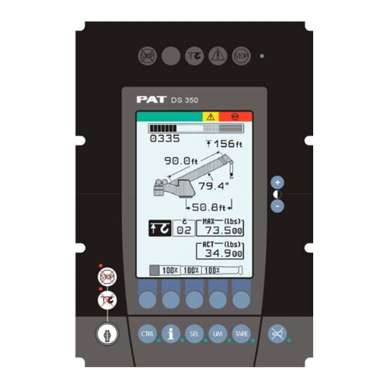
PAT service representative shall be called for repair of the system or reverification of the crane’s LMI calibration. Any structural modifications or changes to the crane shall require reverification of the crane’s LMI calibration. © Hirschmann Rev. E 11/12/08 190147_E... - Page 24 (parts of line) actual load only for cranes with boom control system (The elements are the same on the horizontal display – but in a different order.) © Hirschmann Rev. E 11/12/08 190147_E...
- Page 25 • blinking: range limits exceeded (⇒ see chapter 5.1.4) Symbol wind speed: • Continuously visible: Wind speed value (⇒ see chapter 5.1.5 Error code No. #### E#### (⇒ see chapter 8 "Troubleshooting") © Hirschmann Rev. E 11/12/08 190147_E...
-
Page 26: Limit Setting
Depending on the crane type not all functions listed below are available. Overview limits: Slewing Angle Limitation / Work Area Definition (⇒ chapter 5.1.1) Tip Height Limitation (⇒ chapter 5.1.2) Boom Angle Limitation (⇒ chapter 5.1.3) Radius Limitation (⇒ chapter 5.1.4) © Hirschmann Rev. E 11/12/08 190147_E... -
Page 27: Slewing Angle Limitation / Work Area Definition
• set / delete left slewing angle: Select limit: Select left limit set: delete: Position boom to delete left required left limit angle limit value. program present slewing angle as left limit quit function © Hirschmann Rev. E 11/12/08 190147_E... - Page 28 Display shows symbols and angle values of the programmed slewing angle limit Display shows symbols without angle values quit function © Hirschmann Rev. E 11/12/08 190147_E...
- Page 29 Move the boom tip to one end of the virtual wall you want to set. Sets a point in the working area to start a wall Exits the screen © Hirschmann Rev. E 11/12/08 190147_E...
- Page 30 Move the boom tip to the other end of the additional virtual wall you want to set. Sets the third point to create a second wall Exits the screen and deletes all virtual wall settings © Hirschmann Rev. E 11/12/08 190147_E...
- Page 31 Operation Upon pressing SET, the second wall is created. Accepts the defined walls and exits Allows for further walls to be added Exits the screen and deletes all virtual wall settings © Hirschmann Rev. E 11/12/08 190147_E...
-
Page 32: Tip Height Limitation
Move the tip to delete tip the required height limitation upper limit. present tip height as upper limit Display shows symbol and value of the programmed height limit Display shows symbol without values quit function © Hirschmann Rev. E 11/12/08 190147_E... -
Page 33: Boom Angle Limitation
Display shows symbol with value of the upper angle limit Display shows symbol without value of the upper angle limit quit function © Hirschmann Rev. E 11/12/08 190147_E... - Page 34 Display shows symbol with lower angle limit Display shows symbol without value of lower limit angle quit function © Hirschmann Rev. E 11/12/08 190147_E...
-
Page 35: Radius Limitation
© Hirschmann Rev. E 11/12/08 190147_E... -
Page 36: Wind Speed
5.1.5 Wind Speed This function serves to display the current wind speed. • Battery replacement Please use TRS05 manual 031-300-190-176 for battery replacement. © Hirschmann Rev. E 11/12/08 190147_E... -
Page 37: Info Crane Configuration
Press key "INFO". The display shows the crane symbol representing the adjusted configuration (marked black), the extended operating code number and the reeving number (parts of line). • End function Press again key "INFO". © Hirschmann Rev. E 11/12/08 190147_E... -
Page 38: Display Contrast Control
Press key "OK" to store the momentarily adjusted contrast value and to quit the function. During normal LMI operation the display contrast can be adjusted too by pressing the “+” or “-“ button. © Hirschmann Rev. E 11/12/08 190147_E... -
Page 39: Pre-Operation Inspection And Calibration Verification
In that case the anti two-block switch has to be locked with the red Anti Two-Block Retainer, which is fixed with a red lanyard (not shown) at the anti two-block switch. © Hirschmann Rev. E 11/12/08 190147_E... -
Page 40: Installation Of Anti Two-Block Retainer In Locking Position
3. For storage slide the retainer from right side (5) over the Anti Two-Block switch until the clips (A) lock into the holes (B). Fig. 3: Removal of the Anti Two- Fig. 4: Retainer in Storage Position Block Retainer © Hirschmann Rev. E 11/12/08 190147_E... -
Page 41: Pre-Operation Inspection And Calibration Verification
3. Check that the display of the main boom angle agrees with the actual boom angles. 4. Check that the display of the operating radius of the crane agrees with the actual radius. 5. Check the load display by lifting a load of known weight. © Hirschmann Rev. E 11/12/08 190147_E... -
Page 42: Service And Maintenance
5. Check the pressure transducers at the hoist cylinder(s) and the connecting hoses for oil leakage. Other than correcting the problems identified in the Malfunctions Table and replacing faulty mechanical parts and cables, no other repairs shall be performed by non expert personnel. © Hirschmann Rev. E 11/12/08 190147_E... -
Page 43: Troubleshooting
Center Mid not fully extended Telescope out of permissible sequence flashing …% (tele.) NOTE: If there is any Error Code displayed on the console which is not listed in the Malfunctions Table you shall call the Local Distributor. © Hirschmann Rev. E 11/12/08 190147_E... -
Page 44: Operating Errors
Move boom to permitted area Boom is about to collide with the engine hood, switch off Approaching prohibited area Move boom to permitted area Boom is about to collide with the engine hood, prewarning © Hirschmann Rev. E 11/12/08 190147_E... - Page 45 Swingaway/ swingaway bifold with fly with fly/tele stowed main boom Swingaway/ swingaway/ bifold without bifold without fly stowed on main boom bifold with fly fly stowed on stowed on main boom main boom © Hirschmann Rev. E 11/12/08 190147_E...
-
Page 46: Appendix A: Detailed Symbol Explanation Of Boom Extensions
O.K. button to confirm and to proceed with console programming © Hirschmann Rev. E 11/12/08 190147_E...
Need help?
Do you have a question about the iFLEX5 and is the answer not in the manual?
Questions and answers