
Related Manuals for Hirschmann PRS 40 EZ


Summary of Contents for Hirschmann PRS 40 EZ
- Page 1 HIRSCHMANN PRS 40 EZ OPERATOR’S / SERVICE MANUAL P/N 031-300-190-201 Revision A 03/16/2006...
- Page 3 Operator’s Manual PRS 40 EZ NOTICE Hirschmann, Inc. makes no warranty of any kind with regard to this material, including, but not limited to, the implied warranties of merchantability and/or its fitness for a particular purpose. Hirschmann, Inc. will not be liable for errors contained in this manual or for incidental or consequential damages in connection with the furnishing, performance, or use of this manual.
-
Page 5: Table Of Contents
CREENS 12.1.1 To test the outputs: ..........................38 12.1.2 To test the inputs: ..........................38 12.1.3 Battery level: ............................39 12.2 T ........................40 ROUBLESHOOTING 12.3 T .....................41 ROUBLESHOOTING OISTURE 12.3.1 Water Ingress .............................41 MAINTENANCE ..........................42 © PRS 40 EZ REV A 03/16/06 190201_A... - Page 6 Operator’s / Service Manual, PRS 40 EZ 13.1 ......................42 ATTERY EPLACEMENT PART NUMBERS...........................43 14.1 CONSOLE ..........................43 14.2 A2B .............................44 14.3 WIND ............................46 14.4 ............................47 ANGLE 14.5 A ........................48 NTENNA OPTIONS 14.6 L ............................49 INERIDER 14.7 LOADCELL ..........................50 © PRS 40 EZ REV A 03/16/06...
-
Page 7: General Information
General Information GENERAL INFORMATION The PRS 40 EZ System has been designed to provide indication from various types of sensors, i.e. A2B, Load, Wind and Angle. The A2B system will warn the crane operator of a two-blocking condition of the crane. If a two-blocking... -
Page 8: Features
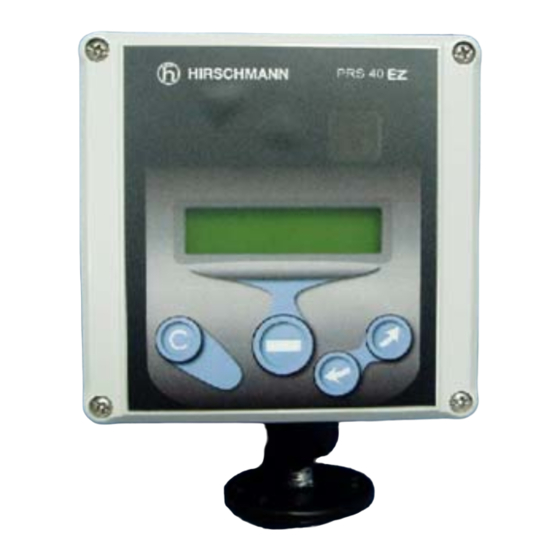
The operator’s console should be mounted in the operator’s field of vision. 4.1.1 Liquid Crystal Display The Liquid Crystal Display (LCD) used in the PRS 40 EZ console is a wide temperature-range graphic display with transflective characteristics that give it a high visibility in sunlight and during backlit night operation. -
Page 9: Control Identification
Generally used to back out of a selection and return to the previous screen. • Pushing this button for more than 1 second will bypass the control lever lockout function of the system. • Accesses the Tare function © PRS 40 EZ REV A 03/16/06 190201_A... -
Page 10: Operation
During the test, the LCD shows the console and system software version. The PRS 40 EZ setup procedure allows the operator to input the sensors being used and the limits for the sensors. The operator must complete the setup procedure for each sensor. -
Page 11: Menu Structure
NOT INSTALLED HARDWIRED RADIO ● OPTIONS ○ TEST SEQUENCE ○ LB/MPH OR KG/KPH ○ ENGLISH OR SPANISH ○ CONTRAST ○ ANALOG INPUT ma/volts ○ BATTERY LEVEL ANGLE A2B1 A2B2 WINDSPEED LOADCELL LINERIDER © PRS 40 EZ REV A 03/16/06 190201_A... -
Page 12: Installation
Operator’s / Service Manual, PRS 40 EZ 4.2.2 Installation The console has a mount that allows the console to be swiveled into any direction and to be mounted in a variety of locations and on nearly any surface. Choose a location that is in view and within reach of the operator. If radio sensors are being used, locate in line of site with the sensor. -
Page 13: Angle
Press and hold the down arrow, . The limits will change to -5 degrees. SETUP/ LIMITS/ ANGLE/ MAXIMUM Press and hold the up arrow, . The limits will change to 90 degrees. © PRS 40 EZ REV A 03/16/06 190201_A... -
Page 14: Installation / Calibration Hardwired
Hardwired (HIRSCHMANN) This is the setup for the standard Hirschmann angle sensor. This angle sensor has a digital output. The angle sensor must be previously installed. Use the setup screens to add the angle sensor to the system. -
Page 15: Calibration
This screen is used to match the angle sensor to the angle of the boom. 2. Scroll to the correct angle and press OK. The calibration and set up of the sensor is then complete. © PRS 40 EZ REV A 03/16/06 190201_A... -
Page 16: Angle
Operator’s / Service Manual, PRS 40 EZ ANGLE This procedure describes how to install and setup a radio angle transmitter. CONTACT CRANE MANUFACTURER FOR WELDING INSTRUCTION PRIOR TO WELDING ON BOOM. Angle sensor, transmitter, and mounting plate. The angle sensor will be mounted on the side of boom so as the boom angle changes, the angle sensor can rotate as shown in the 0°(left) and 90°... - Page 17 It should be ±1°. If it is incorrect, repeat step 5, calibrate the angle sensor again, and verify the actual angle and/or use a different/higher angle (50°) to scroll to and match the angle. © PRS 40 EZ REV A 03/16/06 190201_A...
-
Page 18: A2B
Operator’s / Service Manual, PRS 40 EZ 6.1.1 Operation When an A2B switch has been installed, the status of the switch is always shown. If other sensors are installed besides the A2B, the A2B status will be shown on the right side of the display. - Page 19 1. Check the electrical wiring connecting the various parts of the system for physical damage. 2. Check the anti two-block switches and weights for free movement. © PRS 40 EZ REV A 03/16/06 190201_A...
- Page 20 Operator’s / Service Manual, PRS 40 EZ The following tests shall be performed with care to prevent damage to the machine or injury to personnel. Proper functioning of the system requires successful completion of these tests before operating the machine.
-
Page 21: A2B Limit
H I R SCH MANN A2B 6.1.3 Installation 6.1.3.A Transmitter / Switch The transmitter and battery housing are made of a special polymer that resists damage from impact and will not become brittle even in low temperatures. © PRS 40 EZ REV A 03/16/06 190201_A... - Page 22 Operator’s / Service Manual, PRS 40 EZ 6.1.3.B Transmitter LED The transmitter has an LED on the bottom for diagnostics. The LED should be on when in a two-block condition or when the weight is lifted. The LED will flash rapidly during a 2-block condition and will stop flashing after the switch is in a two-block condition for more than 15 seconds.
-
Page 23: A2B Setup
In order to use the A2B, the A2B sensor must first be set up on with the console. Set the internal DIP switch to: A2B sensor SETUP 4 Add the first A2B sensor to the console by pressing SENSORS/A2B 1/ HARDWIRED. © PRS 40 EZ REV A 03/16/06 190201_A... - Page 24 Operator’s / Service Manual, PRS 40 EZ HARDWIRED A2B WIRING DIAGRAM (EXTERNAL RELAY INSTALLED BY CUSTOMER) © PRS 40 EZ REV A 03/16/06 190201_A...
-
Page 25: Wind
When the system is turned off the peak value will be reset. The peak value can also be reset by pressing the button. © PRS 40 EZ REV A 03/16/06 190201_A... -
Page 26: Limits
Operator’s / Service Manual, PRS 40 EZ 7.1.2 LIMITS The system sets the default speed limit to 20 mph. The limit can be set to any value. The limits are set by selecting SETUP/LIMITS/WIND Use the up and down arrows to set the desired limit. -
Page 27: Wind Setup
Set the internal DIP switch to: Wind speed sensor SETUP 4 Add the wind sensor to the console by pressing SENSORS/ WIND/ HARDWIRED. HARDWIRED WINDSPEED SENSOR WIRING DIAGRAM (EXTERNAL RELAY INSTALLED BY CUSTOMER) © PRS 40 EZ REV A 03/16/06 190201_A... - Page 28 Operator’s / Service Manual, PRS 40 EZ RADIO Add the wind sensor to the console by pressing SENSORS/ WIND/ RADIO. The console will show "SEARCHING". Remove the batteries from the transmitter. Reinstall the batteries into the transmitter. The LED on the transmitter will be on for 3 seconds and then start to flash on and off.
-
Page 29: Loadcell
Enter Setup screen. Select Reeving and press . Use the arrows to adjust the reeving setting. When complete, press Units The load can be displayed in pound or in kilograms. To change the units, press MENU/OPTIONS/LB © PRS 40 EZ REV A 03/16/06 190201_A... -
Page 30: Limits
Operator’s / Service Manual, PRS 40 EZ 8.1.2 LIMITS The unit has no default limit set for the load. The limits are set by selecting SETUP/LIMITS/LOAD Use the up and down arrows to set the desired limit. Press when complete. -
Page 31: Installation
On rest button should be on the load cell side of the plate. Ensure all safety pins are installed properly with washers and bushing to fit the hole diameter and pin length. © PRS 40 EZ REV A 03/16/06 190201_A... -
Page 32: Loadcell Setup
Operator’s / Service Manual, PRS 40 EZ 8.1.4 Loadcell Setup In order to use the loadcell, the loadcell must first be installed into the system. Add the loadcell to the console by pressing HARDWIRED SETUP / SENSORS / INSTALL-REMOVE / LOADCELL / HARDWIRED. - Page 33 ± The system accuracy is to be determined from the following formula: Indicated Load x 100 = % of Load Actual Load © PRS 40 EZ REV A 03/16/06 190201_A...
-
Page 34: Line Rider
Operator’s / Service Manual, PRS 40 EZ LINE RIDER 9.1.1 Operation In order to use the linerider, the linerider must first be installed into the system. See the section on linerider setup. Reeving To view the on hook load display, the correct reeving must be set. -
Page 35: Limits
2. Horizontal movement of the swing arm. 3. Vertical movement of the swing arm. 4. Swivels horizontally around the mounting bolt. The mounting bolt secures the swing arm to the machine. Figure 4. Linerider and Swing Arm. © PRS 40 EZ REV A 03/16/06 190201_A... - Page 36 Operator’s / Service Manual, PRS 40 EZ 9.1.3.A HYDRAULIC BOOM MACHINES Figure 5. Hydraulic Boom Linerider Installation. NOTE: CONTACT CRANE MANUFACTURER FOR WELDING INSTRUCTION PRIOR TO WELDING ON BOOM. 1. Affix the bolt at the tip of the base section on the main boom similar to Figure 5.
- Page 37 11. Connect the linerider extension to the console cable at boom base with the 28ft extension provided. NOTE: Extra electrical extensions can be ordered if required. © PRS 40 EZ REV A 03/16/06 190201_A...
- Page 38 EI33 CONSOLE TO THE PRS 40 EZ. (SEE BELOW) Cable assembly (031-300-060-434) connects to the back of the PRS 40 EZ console and mates with the existing (031-300-101- 178) cable assembly which connects to the linerider. If additional length is required between the console and linerider, cable assemblies of various lengths are available.
-
Page 39: Linerider Setup
6. Pick a known test load as close as possible to the maximum rated load. SAE recommends the test load should be accurate to ±1%. 7. Press CALIBRATIONS/LINERIDER ADJ. 8. Compare the known test load to the displayed load and adjust if necessary using the arrows on the console. © PRS 40 EZ REV A 03/16/06 190201_A... -
Page 40: Radio Module
10.1 INSTALLATION A receiver module must be installed into the PRS 40 EZ before a radio sensor can be set up or used. The following is the procedure for installing the radio module. Caution: Handle the module with care. The module can be damaged by static electricity. Take proper precautions by removing any static electricity from your body. - Page 41 4. Reassemble the console; ensure the wires are not pinched between the lid and the housing. Close housing and tighten the 4 cover screws. Make sure that the console lid is completely seated and properly tightened. © PRS 40 EZ REV A 03/16/06 190201_A...
-
Page 42: Adding Sensors
Operator’s / Service Manual, PRS 40 EZ ADDING SENSORS To add a new sensor, Menu- SETUP/SENSORS/ This gives the sensor select/information screen. It shows the status of all hardware. Each sensor has several options: *NOT INSTALLED HARDWIRED RADIO The status of the sensor is indicated with an "*". In the example, the sensor is "not installed". -
Page 43: Service / Trouble Shooting
When the PRS40 EZ system is turned on, it will show the following screen. This screen shows the telephone number of Hirschmann and the software version. Make sure the display is working and all the lights come on during this time. Listen to the buzzer sound. -
Page 44: Screens
Operator’s / Service Manual, PRS 40 EZ 12.1 SCREENS Communication error screen When working from the normal operating screen and an error occurs, a communication error screen will be displayed temporarily, which indicates loss of communication between a sensor and the console. -
Page 45: Battery Level
The battery level of each radio sensor can be monitored. SETUP >> OPTIONS BATTERY LEVEL. >> Select this option and then press . Each sensor can be selected individually, enabling the user to view the percentage of each sensor’s battery level. © PRS 40 EZ REV A 03/16/06 190201_A... -
Page 46: Troubleshooting
Operator’s / Service Manual, PRS 40 EZ 12.2 TROUBLESHOOTING After the onboard diagnostics have been performed, follow these guidelines All LED's are located inside the receiver box. Problem Cause Solution LCD does not light or No power to Make sure the console is getting power from the crane. -
Page 47: Troubleshooting Moisture
1) Spray Cleaning The enclosures used for the PRS 40 EZ system are water protected to IP 65. This means protection against the environment, such as rain. However, through the use of spray cleaner at short distances, it is possible to force water through the gasket or strain relieves. -
Page 48: Maintenance
Operator’s / Service Manual, PRS 40 EZ MAINTENANCE The only maintenance required is to change the batteries when required. Also, check the mounting hardware daily to ensure that there is no damage. Replace any damaged parts before operating the crane. -
Page 49: Part Numbers
2. 031-300-050-487 3 Washer, Sealing #10 2. 031-300-050-489 3 Nut, #10-24 Lock Nylon Insert 3. 031-300-050-523 1 Fuse, 5 Amp Auto (Mini) 4. 031-300-050-786 1 Gasket, w/ PRS housing & front face © PRS 40 EZ REV A 03/16/06 190201_A... -
Page 50: A2B
Operator’s / Service Manual, PRS 40 EZ 14.2 031-300-060-593 Radio A2B transmitter assembly 031-300-060-586 Antenna only Radio A2B transmitter 031-300-050-688 031-300-050-763 Neoprene rubber gasket © PRS 40 EZ REV A 03/16/06 190201_A... - Page 51 Part Numbers 031-002-060-022 Radio A2B switch 031-300-050-295 A2B Mounting standoff 031-300-050-264 A2B mounting plate 031-300-050-272 Lynch pin © PRS 40 EZ REV A 03/16/06 190201_A...
-
Page 52: Wind
Operator’s / Service Manual, PRS 40 EZ 14.3 WIND 031-300-050-321 031-300-050-480 Mounting pole Anemometer mounting plate 031-300-050-322 031-300-060-586 Transmitter 031-300-050-323 031-300-050-507 Retaining pin Sensor © PRS 40 EZ REV A 03/16/06 190201_A... -
Page 53: Angle
Part Numbers 14.4 ANGLE 031-300-060-695 Sensor Assy, Angle w/ 25’ Cable 031-300-060-592 Sensor, Angle w/ Transmitter 031-300-050-577 Plate, Radio Angle Mounting © PRS 40 EZ REV A 03/16/06 190201_A... -
Page 54: Antenna Options
Operator’s / Service Manual, PRS 40 EZ 14.5 ANTENNA OPTIONS Mount antennas in identical positions and in a direct line between transmitter and receiver, ensuring that no obstructions will interfere with the transmission of the radio signal. 031-300-050-671 ANTENNA, 918 MHz FOR... -
Page 55: Linerider
Part Numbers 14.6 LINERIDER Linerider * Please contact Hirschmann, ECS with questions concerning repair or replacement of component. (717) 263-7655 031-300-060-434 Extension cable 031-300-101-178 © PRS 40 EZ REV A 03/16/06 190201_A... -
Page 56: Loadcell
Operator’s / Service Manual, PRS 40 EZ Sensor cable 14.7 LOADCELL 7.5t (15k) RADIO LOAD CELL The load cell kit will include item 1, item 2, and one of the optional item 3. ITEM PART NUMBER DESCRIPTION 031-300-060-608 1.00 SENSOR ASSY, FORCE TRANS. 7.5T W/RADIO TRANSMITTER 031-300-050-064 1.00... - Page 57 PIN/BUSHINGS, 1 5/8" FOR 40 KRADIO LOADCELL 7/8" 1.00 OPTION 031-300-050-563 ROPE 1.00 OPTION 031-300-050-604 PIN/BUSHINGS, 1 1/2" FOR 40K RADIO LOADCELL * Please contact Hirschmann, ECS with questions concerning repair or replacement of component. (717) 263-7655 © PRS 40 EZ REV A 03/16/06 190201_A...
Need help?
Do you have a question about the PRS 40 EZ and is the answer not in the manual?
Questions and answers