Sign In
Upload
Manuals
Brands
Hirschmann Manuals
Music Mixer
PAT IFLEX5
Hirschmann PAT IFLEX5 Manuals
Manuals and User Guides for Hirschmann PAT IFLEX5. We have
2
Hirschmann PAT IFLEX5 manuals available for free PDF download: Service Manual, Operator's Manual
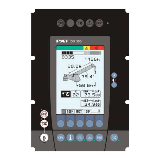
Hirschmann PAT IFLEX5 Service Manual (79 pages)
LOAD MOMENT INDICATOR
Brand:
Hirschmann
| Category:
Touch Panel
| Size: 3 MB
Table of Contents
Table of Contents
4
1 General Information
7
2 Warnings
7
3 Description of the System
8
Description of System Function
8
Description of a Can Bus System
8
Description of the System Components
9
4 What's Wrong
10
Ihave an Error Code Indicated on the Console
10
The Displayed Angle Does Not Match the Actual Boom Angle
10
The Displayed Length Does Not Match the Actual Boom Length
10
The Displayed Slewing Does Not Match the Actual Slewing Angle
10
The Displayed Load Does Not Match the Actual Load
10
The Console Display Is Blank
10
Ihave an A2B Problem
10
I Havea Can-Bus Problem
10
Ineed to Identify a Spare Part
10
5 Angle Sensing
11
Angle Sensing Error - Flow Chart
12
6 Length Sensing
14
Length Sensing Error - Flow Chart
15
7 Pressure Sensing
17
Pressure Sensing Error - Flow Chart
17
8 Slewing Sensing
18
Slew Sensing Error - Flow Chart
19
9 Load Sensing
20
Load Sensing Error - Flow Chart
20
10 No Console Display
21
11 A2B Problem
22
12 Cann-Bus Communication
23
E61
23
E61 - Flow Chart
24
E62
25
E63
25
E64
25
E64 - Flow Chart
26
E65
26
13 Troubleshooting a Sensor Problem Using the Display
27
14 Iflex5 Boom Control System (BCS)
30
Rt9000E / Rt800E Basics
30
Terminology
30
Components
30
Manual / Auto Mode
30
Tele Sequence
32
Iflex5 Bcs Digital Inputs
32
Rt9000E / Rt800E Iflex5 Bcs Digital Outputs
33
Iflex5 Bcs Analog Inputs and Pwm Outputs
35
Iflex5 Bcs Test Display
37
Boom out of Sequence
38
Tele Rod Drain Valve
38
Tele Two Stage Relief Valve
38
Hydraulic Luffing Boom Extension
39
15 Drawings
40
Components of the Lmi System Pat Iflex5
40
Block Diagram
41
Electrical System Diagram Standard System
42
Central Unit to Crane and Console Wiring Diagram
42
Cable Reel (Length/Angle Sensor) Wiring Diagram
43
Boom Extension Anti-Two Block Wiring Diagram
44
Main Central Unit Connector
44
Electrical System Diagram Boom Control System
45
Central Unit to Crane Interface Wiring Diagram
45
Console and Sensor Wiring Diagram
46
Cable Reel (LWG520/0002) Wiring Diagram
48
Luffer Extension Wiring Diagram
49
16 Spare Part Listings
50
Central Unit, Iflex5 Part No. 021-020-060-003
50
Graphic Console Assy, Vertical Part No. 050-350-061-356
51
Graphic Console Assy, Part No. 050-350-061-376
52
Cable Reel, Lwg508 Part No. 068-508-060-001
53
Cable Reel, Lwg521 Part No. 068-521-060-002
55
Cable Reel, Lwg152 Part No. 067-152-060-056
56
Pressure Transducer Block, Dav314/0014 Part No. 044-314-060-014
57
Cable Assembly 11M, Part No. 031-010-101-007
57
Wiring Harness Standard, Part No. 031-010-100-549
57
Wiring Harness Boom Control, Part No. 031-010-100-554
58
Cable Assembly, 14M Part No. 031-010-100-555
58
Trs05 Repeater, Radio Windspeed Kit 031-300-104-087
59
17 Service Screen for Sensor Calibration
60
Activating the Service Screen for Sensor Calibration
60
Zero-Setting the Transducer Inputs
61
Zero-Setting the Slewing Inputs
61
Length Sensor Calibration Procedure
62
Cable Reel LWG508 Adjustment Procedure
62
Length Sensor Adjustment Procedure
63
Cable Reel Length Cable Replacement Procedure
64
Angle Sensor Calibration Procedure
65
Zero-Setting the Slew Potentiometer
67
18 Error Codes
68
19 Troubleshooting Moisture
78
Water Ingress
78
Condensation
79
Advertisement
Hirschmann PAT IFLEX5 Operator's Manual (46 pages)
PAT LOAD MOMENT INDICATOR vertical / horizontal console
Brand:
Hirschmann
| Category:
Music Mixer
| Size: 1 MB
Table of Contents
Table of Contents
5
1 General Information
7
2 Warnings
7
3 System Description
8
System Function
10
Operating Console
11
Control Identification
11
4 Configuration Setup
17
Lmi Setup Procedure
17
Quick Setting of the Reeving
21
Quick Hoist Line Selection
22
5 Operation
23
Limit Setting
26
Slewing Angle Limitation / Work Area Definition
27
Tip Height Limitation
32
Boom Angle Limitation
33
Radius Limitation
35
Wind Speed
36
Info Crane Configuration
37
Display Contrast Control
38
6 Pre-Operation Inspection and Calibration Verification
39
Machines with Only a Main Hoist
39
Machines with Main and Auxiliary Hoists
39
Installation of Anti Two-Block Retainer in Locking Position
40
Removal and Storage of the Anti Two-Block Retainer
40
Pre-Operation Inspection and Calibration Verification
41
7 Service and Maintenance
42
8 Troubleshooting
43
General
43
Malfunction Table
43
Operating Errors
44
Error
44
10 Appendix B:detailed Symbol Explanation of Counterweight Options
46
9 Appendix A: Detailed Symbol Explanation of Boom Extensions
46
Advertisement
Related Products
Hirschmann iSCOUT expert compact
Hirschmann PAT 050-350-061-351
Hirschmann PAT 050-350-061-354
Hirschmann PAT 050-350-061-355
Hirschmann IRD 8500
Hirschmann iVISOR mentor QVGA
Hirschmann qSCALE i2
Hirschmann IRD 8500/QP
Hirschmann IRD 8500/QA
Hirschmann IRD 8500/OF
Hirschmann Categories
Switch
Network Router
Control Unit
Wireless Access Point
Antenna
More Hirschmann Manuals
Login
Sign In
OR
Sign in with Facebook
Sign in with Google
Upload manual
Upload from disk
Upload from URL