
Related Manuals for CIRCLE FITNESS M-7 SERIES E TYPE


Summary of Contents for CIRCLE FITNESS M-7 SERIES E TYPE
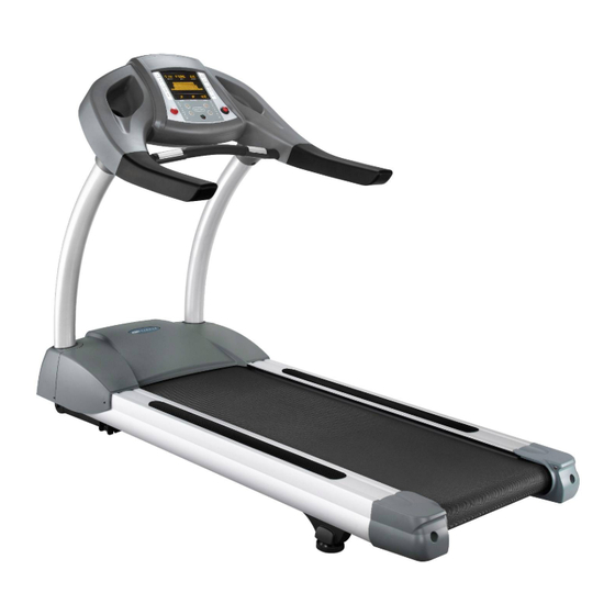
- Page 1 Document NO. M-7E-EM-English Engineer Manual-Trouble Shooting PAGE Page 1 of 25 VERSION ENGINEER MANUAL FOR AFTER SALE SERVICE PRODUCT:TREADMILL MODEL: M-7 SERIES E TYPE...
-
Page 2: Table Of Contents
Document NO. M-7E-EM-English Engineer Manual-Trouble Shooting PAGE Page 2 of 25 VERSION INFORMATION GUIDE: 1. Error Signal Check Steps And Solutions 1.1 Error Signal: 『LS』 ----- Page 3~7 1.2 Error Signal: 『E1』 ----- Page 8 1.3 Error Signal: 『E2』 ----- Page 8~9 2. - Page 3 Document NO. M-7E-EM-English Engineer Manual-Trouble Shooting PAGE Page 3 of 25 VERSION 1. Error Signal Check Steps And Solutions 1.1. 【LS】 :Can not receive signal from speed sensor over 8 seconds while workout, all windows display will off, all output will stop, and show 【LS】 on TIME window. ※If this is a all new product that just finished assemble, there are more possibly in assemble problems, maybe connect wire not well or wire damaged while assemble.
- Page 4 Document NO. M-7E-EM-English Engineer Manual-Trouble Shooting PAGE Page 4 of 25 VERSION Step illustrate Auxiliary Photo Press STOP then press START and FAST simultaneously immediately, to leave you hand from keys till dot-matrix window show WELCOME. LED display windows will do the scan mode after show WELCOME.
- Page 5 Document NO. M-7E-EM-English Engineer Manual-Trouble Shooting PAGE Page 5 of 25 VERSION Step illustrate Auxiliary Photo Do it can be calibrate normally or show LS Calibrate abnormal, show 【LS】 on TIME window? Calibrate normal, return to idle mode If calibrate normally and return to idle mode, please check the SPEED parameter on CALORIES window when calibrate speed at max speed 20km/h(±0.1).
- Page 6 Document NO. M-7E-EM-English Engineer Manual-Trouble Shooting PAGE Page 6 of 25 VERSION Step illustrate Auxiliary Photo Open the motor cover then ON the AC power, press START to begin and check the pilot lamp on interface PCB. 1. Is the LED7 light up before show 【LS】 ? 2.
- Page 7 Document NO. M-7E-EM-English Engineer Manual-Trouble Shooting PAGE Page 7 of 25 VERSION Step illustrate Auxiliary Photo If all function are normal and no error signal after reset power, it maybe cause by power core, maybe power core connect not well, please check the power core. If all function are normal and no error signal after reset power, maybe the loading is too heavy and inverter to start...
- Page 8 Document NO. M-7E-EM-English Engineer Manual-Trouble Shooting PAGE Page 8 of 25 VERSION 1.2. 【E1】 :When memory device damaged or read or write had program, all window display will be off and all output will be stop and show【E1】on TIME window, show【EEPROM ERROR】...
- Page 9 Document NO. M-7E-EM-English Engineer Manual-Trouble Shooting PAGE Page 9 of 25 VERSION Step illustrate Auxiliary Photo Check the console wire, damage or connect Refer to 2.2『Console Wire』 terminal problem. After check or reconnect or replace the wire, back to execute step 1 to check. After check or reconnect or replace the Refer to 2.5『Incline Motor』...
-
Page 10: Interface Pcb
Document NO. M-7E-EM-English Engineer Manual-Trouble Shooting PAGE Page 10 of 25 VERSION 2. Information For Components 2.1. Interface PCB: 2.1.1.Appearance and connector description: Console wire Speed sensor wire Incline VR wire AC power input Inverter AC power 90~240Vac LED2 Incline UP LED4 LED7 LED6... -
Page 11: Interface Pcb
Document NO. M-7E-EM-English Engineer Manual-Trouble Shooting PAGE Page 11 of 25 VERSION 2.1.3.Interface PCB function check: 2.1.3.1. Check incline function Step illustrate Auxiliary Photo OFF the AC power, to pull out the console wire and incline motor power wires, then ON the AC power, measure the terminal UP &... - Page 12 Document NO. M-7E-EM-English Engineer Manual-Trouble Shooting PAGE Page 12 of 25 VERSION Step illustrate Auxiliary Photo Connect back the console wire, pull out the Short the black and orange wire PINs incline motor power wires only, press (PIN 1 and PIN 4) start to quick start, short the console wire PINs for incline UP by metalwork, to measure terminals UP &...
- Page 13 Document NO. M-7E-EM-English Engineer Manual-Trouble Shooting PAGE Page 13 of 25 VERSION 2.1.3.2. Check speed output device Step illustrate Auxiliary Photo Switch ON the AC power, short the enable motor component by metalwork and keep on. Short the motor fast component by metalwork, then metalwork leave the motor fast component (open), to do 5~10 times Short the enable motor component...
- Page 14 Document NO. M-7E-EM-English Engineer Manual-Trouble Shooting PAGE Page 14 of 25 VERSION Step illustrate Auxiliary Photo To continue, do not move out and keep on short the enable motor component.(Motor in the rotating condition) Short the motor slow component by metalwork, then metalwork leave the motor Do not move out and keep on short the enable Do not move out and keep on short the enable...
- Page 15 Document NO. M-7E-EM-English Engineer Manual-Trouble Shooting PAGE Page 15 of 25 VERSION 2.1.3.3. Check power supply for console Step illustrate Auxiliary Photo Switch ON the AC power, check the pilot lamp, it shall be full light up in the normal condition. It shall not flash or slight light up.
- Page 16 Document NO. M-7E-EM-English Engineer Manual-Trouble Shooting PAGE Page 16 of 25 VERSION 2.2. Console wire check: 2.2.1.Check all connect certainty and outward completely. Step illustrate Auxiliary Photo To pull out the console wire connector plug. Check connector internal PINs, it shall not be crooked.
-
Page 17: Speed Sensor
Document NO. M-7E-EM-English Engineer Manual-Trouble Shooting PAGE Page 17 of 25 VERSION 2.3. Speed sensor check: 2.3.1.Check all connect certainty. Step illustrate Auxiliary Photo Check the connector connection with interface PCB certainly. Check connector internal PINs, it shall not be draw back. 2.3.2.Check outward completely and function normal. -
Page 18: Inverter
Document NO. M-7E-EM-English Engineer Manual-Trouble Shooting PAGE Page 18 of 25 VERSION 2.4. Inverter check: Step illustrate Auxiliary Photo Switch ON the AC power and to check the fan where on the inverter. It shall be operate when power ON and stop when power OFF. -
Page 19: Incline Motor
Document NO. M-7E-EM-English Engineer Manual-Trouble Shooting PAGE Page 19 of 25 VERSION Step illustrate Auxiliary Photo To continue, switch OFF the AC power, to connect the incline motor wires white one and black one to inverter power source terminal. Switch ON the AC power, the incline motor shall be operate in the normal condition. -
Page 20: Membrane Key
Document NO. M-7E-EM-English Engineer Manual-Trouble Shooting PAGE Page 20 of 25 VERSION 2.6. Membrane key Step illustrate Auxiliary Photo To pull out the connection from console PCB. If mull-function when you are using, please find the PINs definition for keys terminal as below. -
Page 21: 3. Engineering Mode
Document NO. M-7E-EM-English Engineer Manual-Trouble Shooting PAGE Page 21 of 25 VERSION 3. Engineering Mode 3.1. Engineering Mode ONE: Factory Settings 3.1.1.To pull out the emergency stop key then press START and FAST simultaneously and put the emergency key back, to leave you hand from keys till dot-matrix window show WELCOME. - Page 22 Document NO. M-7E-EM-English Engineer Manual-Trouble Shooting PAGE Page 22 of 25 VERSION 3.1.3.Press START to begin speed calibration. 3.1.3.1. The dot-matrix window show『SPEED CALIBRATION』when calibrating. 3.1.3.2. CALORIES window show speed parameter, SPEED show real speed value, TIME window show front roller RPM, speed parameter shall between 340~350 at max speed 20KPH in the normal condition.
-
Page 23: Real Speed Do Not To Fit In With Display Speed
Document NO. M-7E-EM-English Engineer Manual-Trouble Shooting PAGE Page 23 of 25 VERSION 4. Other Information 4.1. Real Speed Do Not To Fit In With Display Speed Step illustrate Auxiliary Photo To START and operate the speed to the position where has problem. To measure the running belt speed to compare to display speed. -
Page 24: Abnormal Display On Console
Document NO. M-7E-EM-English Engineer Manual-Trouble Shooting PAGE Page 24 of 25 VERSION 4.3. Abnormal Display On Console Step illustrate Auxiliary Photo Switch ON the power and press START to quick start, if the motor work normal, just display abnormal, please replace the console PCB. -
Page 25: Membrane Key Lose Function
Document NO. M-7E-EM-English Engineer Manual-Trouble Shooting PAGE Page 25 of 25 VERSION 4.5. Membrane Key Lose Function Step illustrate Auxiliary Photo Open the console and pull out the membrane connector from console PCB. To refer to the PIN table of 2.6『Membrane Key』, to find PINs on console PCB that got problem while operate and short them.
Need help?
Do you have a question about the M-7 SERIES E TYPE and is the answer not in the manual?
Questions and answers