
Related Manuals for Mitsubishi Electric Procon IO-INTERFACE


Summary of Contents for Mitsubishi Electric Procon IO-INTERFACE
-
Page 1: Installation Manual
Procon IO-INTERFACE FOR INSTALLERS INSTALLATION MANUAL Version 1.01 For safe and correct use, please read this installation manual thoroughly before installing the PROCON IO-INTERFACE. MITSUBISHI ELECTRIC... - Page 2 Page 2 of 24...
-
Page 3: Table Of Contents
Contents Safety Precautions ............................... 8 Product Overview ..............................9 2.1. Basic Features .............................. 9 2.2. Extended features ............................9 2.3. Advanced Energy Save Features........................9 2.4. Relay Output ..............................9 Supplied Wiring Looms............................10 Size and weight..............................10 Electrical wiring and installation ........................11 5.1. - Page 4 [Fig. 1] Included Items 1 x Procon IO-Interface 1 x Manual Page 4 of 24...
- Page 5 [Fig. 2] Inside of Units Digital Inputs Analogue Inputs Dip Switch Digital Outputs Status LEDs Page 5 of 24...
- Page 6 [Fig. 3] Wiring Diagram On/Off Faults Lock Thermo Energy Save Heat/Cool External Fault Setpoint Mode Fan Speed CN105 or CN92 INDOOR UNIT PCB Page 6 of 24...
- Page 7 Quick set up Step 1: Unpack the Procon IO-Interface and secure it in place. Step 2: Set the dip switches on the Procon IO-Interface depending of the requirements. Step 3: Connect inputs and outputs depending of the requirements. Step 4: Connect the Procon IO-Interface to the CN105 terminal on the indoor unit.
-
Page 8: Safety Precautions
Do not reconstruct or change the settings of the protection devices • - If the protection device is shorted or operated forcibly, or parts other than those specified by Mitsubishi Electric are used, fire or explosion may result To dispose of this product, consult your dealer •... -
Page 9: Product Overview
2. Product Overview The Procon IO-Interface unit is a versatile interface module for use on equipment fitted with either a CN105 or CN92 terminal. The unit features Digital-Analogue Input / Digital Output and can provide a wide range of control features with bit switch selection as detailed below: 2.1. -
Page 10: Supplied Wiring Looms
The unit is provided with a 1.5 meter five wire connection loom to connect from the IO-Interface to CN105 or CN92 on the associated air conditioner. The loom is already internally connected to the IO-INTERFACE and has a plug on the free end. 4. Size and weight The Procon IO-Interface details are: Height 138 mm Width... -
Page 11: Electrical Wiring And Installation
5. Electrical wiring and installation 5.1. Precautions on electrical wiring Warning: Electrical work should be done by qualified electrical engineers / electrician in accordance with "Engineering Standards for Electrical Installation" and supplied installation manuals. Dedicated circuits should also be used. If the power circuit lacks capacity or has an installation failure, it may cause a risk of electric shock or fire. -
Page 12: External Connections
5.3. External Connections 5.3.1. Digital inputs The four digital inputs are: Lock Energy Save Remote Fault The four inputs are all activated by contact closure. The switching voltage is 5v DC at approx 1mA. 5.3.2. Analogue Inputs The three analogue inputs are: Setpoint Mode Fan Speed... -
Page 13: Description Of Features
6. Description of Features 6.1. Basic Parameter Control The unit has a digital input for control of On/Off and three analogue inputs for control of Setpoint, Mode and Fan Speed. A change to any of these inputs will be transmitted to the air conditioner. The analogue inputs work in bands. -
Page 14: Dead Band Mode
The diagram below shows an example of the Auto/Fan function. 6.3.2. Dead Band Mode Dead Band mode is selected by setting bit switch SW2-1 to ON and activating the ‘Energy Save’ input. In this mode the unit uses high and low setpoints to control the operation of the air conditioner. The selected parameter values for Setpoint and Mode are ignored by the system. -
Page 15: Relay Outputs
6.4. Relay Outputs There are 4 relay outputs each of which has an associated LED 6.4.1. On/Off The relay and the LED both energise when the unit is ON and de-energise when it is off. The LED will flash when the unit is ON but in standby mode. -
Page 16: Led Indications On The Unit
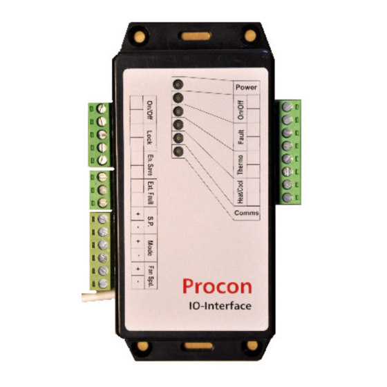
7. LED Indications on the Unit LED1 is the top LED. The unit has 6 LEDs which are all visible through the case of the unit. Their functions are: LED1: ‘Power’ - Blue During the establishing of communications this LED will flash approximately once per second. Once communication is established the LED will remain permanently ON LED2 : ‘Run’... -
Page 17: Applicable Air Conditioning Models
8. Applicable Air Conditioning Models Below is a list of Air Conditioning models that can be connected to this unit: M series product range (includes MXZ) Mr Slim product range (includes S series) * Please note that: T he split units must have CN92 / CN105 connection. This connection is only on units produced on or after 2006 8.1. -
Page 18: Using Single Splits In A Group
8.2. Using single splits in a group It is recommended to use one IO-Interface per indoor unit, however if the fault output is not used one IO-Interface can be used per twin / triple / quad system. When using Fault output 8.2.1. -
Page 19: Using Mxz Splits
8.3. Using MXZ splits One IO-Interface must be installed per indoor unit when using a MXZ system. IO Interface IO Interface IO Interface Page 19 of 24... -
Page 20: Important Notes
9. Important Notes The cable used to connect the IO-Interface to the indoor unit cannot be extended as it is low voltage − The split units must have CN92 / CN105 connection. This connection is only on units produced on or after −... -
Page 21: Additional Information
Additional Information 10.1. Appendix A: Analogue Input Ranges 10.1.1. Setpoint: Temp Volts Valid setpoint ranges are: AUTO 19 to 28 degrees HEAT 17 to 28 degrees COOL 19 to 30 degrees If the input is outside the valid range then the air conditioner will use the nearest available setpoint. 10.1.2. -
Page 22: Sw2-1 To Sw2-5 Energy Save Settings - Auto/Fan Algorithm
10.2.2. SW2-1 to SW2-5 Energy Save Settings - Auto/Fan Algorithm SW2-1 OFF: Auto/Fan Algorithm SW2-2 and SW2-3 OFF: Algorithm Inactive SW2-2 ON, SW2-3 OFF: AUTO time = 0.5 Hrs SW2-2 OFF, SW2-3 ON: AUTO time = 1.0 Hrs SW2-2 ON, SW2-3 ON: AUTO time = 2.0 Hrs Summary: SW2-1... -
Page 23: Sw2-5 Reset Settings When Energy Save Deadband Mode Is Not Required
SW2-4 and SW2-5 Reset settings when energy save deadband mode is not 10.2.4. required To retain fan coil values through a power out set SW2-4 and SW2-5 both OFF. To re-load fan coil values from the IO_Interface inputs after a power out set SW2-4 ON and SW2-5 ON. This option is not available (or needed) when using Energy Save Deaband Mode. - Page 24 • Low Voltage Directive 73/23/EEC • Electromagnetic Compatibility Directive 89/336/EEC Please be sure to put the contact address/telephone number on this manual before handing it to the customer. MITSUBISHI ELECTRIC UK MITSUBISHI ELECTRIC UK, TRAVELLERS LANE, HATFIELD HERTFORDSHIRE, AL10 8XB Page 24 of 24...
Need help?
Do you have a question about the Procon IO-INTERFACE and is the answer not in the manual?
Questions and answers