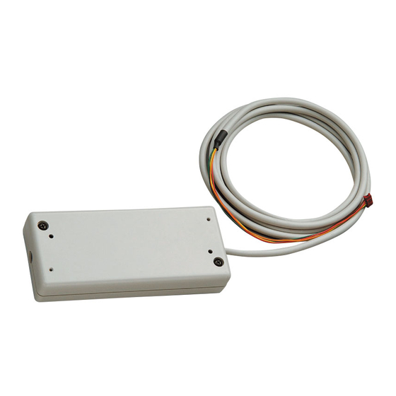
Mitsubishi Electric MAC-333IF-E Technical Manual
System control interface
Hide thumbs
Also See for MAC-333IF-E:
- Installation manual (22 pages) ,
- Installation manual (196 pages)

Related Manuals for Mitsubishi Electric MAC-333IF-E


Summary of Contents for Mitsubishi Electric MAC-333IF-E
- Page 1 S Y ST EM C ON TR OL IN TE RFAC E MAC-333IF-E M od el TECHNICAL MANUAL 2012...
- Page 3 Table of Contents MAC-333IF-E (SYSTEM CONTROL INTERFACE) 1 PRODUCT SPECIFICATIONS ··················································································································································2 2 INSTALLATION OF INTERFACE UNIT ····································································································································4 3 CONNECTION ··········································································································································································4 4 SETTING OF DIP SWITCH AND ROTARY SWITCH ················································································································7 5 FUNCTIONS ··············································································································································································8 5.1 M-NET CONNECTION ····················································································································································8 5.2 MA REMOTE CONTROLLER CONNECTION ················································································································9 5.3 REMOTE CONTROL ····················································································································································11...
-
Page 4: Product Specifications
1 PRODUCT SPECIFICATIONS (1) Function table This product enables the following function. Function name Description MA remote controller connection Connecting M-series to the wired remote controller (MA remote controller). Centralized control of M-series and other series with P-series/City Multi-series. M-NET connection (Including ME remote controller connection) Remote control Linking and operating with an open/close switch, such as a card key. -
Page 5: Power Supply
CONNECTION" in this manual. CONTROLLER CONNECTION” in this manual. (2) Specifications Item Model MAC-333IF-E Power supply 12 VDC, Indoor power-receiving system 54(H) × 160(W) × 70(D)mm Dimensions 0 to 40 ºC (32 to 104 ºF), no condensation, indoor use only... - Page 6 2 INSTALLATION OF INTERFACE UNIT • The Interface unit should be placed in a location where the connecting cable (5-core) from the interface unit can reach the indoor unit. • The device will not function properly if the connecting cable (5-core) is extended, so do not extend the connecting cable (5-core). •...
- Page 7 Mounting screw (2) Connecting to the systems Cable clamp • Before performing the following procedures, turn off the main power to the air conditioner and all systems. • If the connecting cable is not securely fi xed, the connector may come off, and the interface could break or malfunction.
- Page 8 Power supply unit output such as relay controller DC power source (12V) TB571 TB530 TB520 Card key, SYSTEM CONTROL Interface Coin timer, CN591 MAC-333IF-E etc. Remote control TB580 CN560 MA remote controller CN105 MA remote controller (CN92) connection Indoor control board...
- Page 9 4 SETTING OF DIP SWITCH AND ROTARY SWITCH • Set the switches before turning on the power. The interface unit will not work normally if the switches are not set correctly. Rotary switches (SW501, SW510) … M-NET address setting SW No. M-NET Address Description SW510...
- Page 10 5 FUNCTIONS 5.1 M-NET CONNECTION Function MELANS system controller using M-NET communication control enables the centralized/separate control of the summary room air conditioner with the packaged air conditioner (P-series and City Multi-series). System MXZ-series configuration Outdoor unit Outdoor unit outdoor unit P-series P-series Indoor unit...
- Page 11 MAC333IF-E Indoor control board in the room air conditioner Connecting cable that comes with MAC-333IF-E MA remote controller Switch setting To operate one indoor unit with the MA remote controller, the following switch setting is required. * To operate more than one air conditioner using group setting with the MA remote controller, refer to 5.2 “MA REMOTE CONTROLLER CONNECTION”...
- Page 12 (2) Group operation using the MA remote controller Function A maximum of 16 indoor units can be operated in the group operation using the MA remote controller. summary System Outdoor unit Outdoor unit configuration MXZ-series outdoor unit Indoor unit Indoor unit Indoor unit Indoor unit MAC333IF-E...
-
Page 13: Remote Control
5.3 REMOTE CONTROL (1) Card key connection (Switch will open by insertion of the card key.) Function Switch will open by insertion of the card key, which stops the room air conditioner. summary System The card key must be the one that configuration ·... - Page 14 (2) Card key connection (Switch will close by insertion of the card key.) * Card key connection can be linked with the open/close switch of the window. Function Switch will close by insertion of the card key, which stops the room air conditioner. summary System The card key must be the one that...
- Page 15 (3) Coin timer connection (Switch will close after a coin is inserted.) Function Switch will close after insertion of a coin, which starts/stops the room air conditioner. summary System Coin timer must be the one that SYSTEM CONTROL Interface configuration ·...
- Page 16 (4) Coin timer connection (Switch will open after a coin is inserted.) Function Switch will open after insertion of a coin, which starts/stops the room air conditioner. summary Coin timer must be the one that System SYSTEM CONTROL Interface · opens the switch when inserted. configuration MAC333IF-E ·...
- Page 17 The operation can be started/stopped or enabled/disabled according to the last operation performed by continuous contact switches. summary System SYSTEM CONTROL Interface configuration MAC-333IF-E · The switches can be used on the following condition: 12 VDC, 0.5 to 2.0 mA CN591 Brown...
- Page 18 (6) Details of remote control (for giving priority to operation performed by continuous contact switch) Function The operation can be started/stopped or enabled/disabled according to the operation by continuous contact switches. summary System SYSTEM CONTROL Interface configuration MAC333IF-E · The switches can be used on the following condition: 12 VDC, 0.5 to 2.0 mA CN591 Brown...
- Page 19 (7) Details of remote control (Operations using instantaneous contact switches: ON/OFF operation, disabling/enabling manual operation) Function Using instantaneous contact switches, operation can be switched between the ON/OFF and disabling/enabling the manual operation. summary System SYSTEM CONTROL Interface MAC333IF-E configuration · The switches can be used on the following condition: 12 VDC, 0.5 to 2.0 mA CN591 Brown...
- Page 20 (8) Details of remote control (ON/OFF operation with instantaneous contact) Function Using instantaneous contact switches, the room air conditioner can be turned On and OFF. summary System SYSTEM CONTROL Interface configuration MAC333IF-E · The switches can be used on the following condition: 12 VDC, 0.5 to 2.0 mA CN591 Brown...
- Page 21 (9) Details of remote control (HEAT/COOL input) Function The operation can be switched between ON/OFF and HEAT/COOL according to the last operation performed by continuous contact switches. summary System SYSTEM CONTROL Interface configuration MAC333IF-E · The switches can be used on the following condition: 12 VDC, 0.5 to 2.0 mA CN591 Brown...
-
Page 22: Status Signal Output
5.4 STATUS SIGNAL OUTPUT (1) Relay outputs of ON/OFF operation signal and normal/abnormal signal Function ON/OFF signal and normal/abnormal signal of the room air conditioner can be output to the relay. summary System SYSTEM CONTROL interface configuration MAC333IF-E Relay 1, 2 TB571 Coil rating: 12 VDC, 75 mA or less TB530... - Page 23 (2) LED indications of ON/OFF operation signal and normal/abnormal signal Function ON/OFF signal and normal/abnormal signal of the room air conditioner can be indicated using LED. summary System SYSTEM CONTROL interface configuration MAC333IF-E TB571 Resistance 1 LED 1 Resistance 2 TB530 LED 2 LED 1, 2 : Select LED which illuminates around 10 mA.
- Page 24 (3) Relay outputs of ON/OFF operation signal and heater control signal Function ON/OFF signal of the room air conditioner and heater control (ON/OFF) signal can be output to the relay. summary System SYSTEM CONTROL interface configuration MAC333IF-E Relay 1, 2 TB571 Coil rating: 12 VDC, 75 mA or less TB530...
- Page 25 (4) Relay outputs of ON/OFF signal and humidifier control signal Function ON/OFF signal of the room air conditioner and humidifier control (ON/OFF) signal can be output to the relay. summary System SYSTEM CONTROL interface configuration MAC333IF-E Relay 1, 2 TB571 Coil rating: 12 VDC, 75 mA or less TB530 Relay 2...
- Page 26 (5) Relay outputs of heater control signal and humidifier control signal Function Control (ON/OFF) signal of the external heater and the external humidifier can be output to the relay. summary System SYSTEM CONTROL interface configuration MAC333IF-E Relay 1, 2 TB571 Coil rating: 12 VDC, 75 mA or less TB530 Relay 2...
- Page 27 · The air conditioner remains off when the main power is turned on. * When the “AUTO restart function” is enabled on the air conditioner, set this function to SW500-2 OFF on MAC-333IF-E, and the air conditioner operates according to the setting on the air conditioner. · ON: ·...
-
Page 28: Important Note
When several air conditioners are set in the same group using the M-NET system controller, P-series and City multi-series can not be included in the group. MAC-399IF-E and MAC-333IF-E can be set in the same group using the M-NET system controller, but the MA remote controller and the wireless remote controller cannot be used on MAC-333IF-E. -
Page 32: Sy S T E M C On Tro L In Terface
SY S T E M C ON TRO L IN TERFACE MAC-333I F-E M od e l TECHNICAL MANUAL HEAD OFFICE: TOKYO BLDG.,2-7-3, MARUNOUCHI, CHIYODA-KU, TOKYO 100-8310, JAPAN New publication effective Sep. 2012 Issued in Sep. 2012 M-R0598 SIZ1209<MEE> Specifications are subject to change without notice.
Need help?
Do you have a question about the MAC-333IF-E and is the answer not in the manual?
Questions and answers